
New energy commercial vehicle energy efficient recovery system

A recovery system and commercial vehicle technology, applied in the field of new energy commercial vehicle braking energy recovery system, can solve the problems of brake wear, small brake pedal working angle, low charging efficiency, etc., and achieve the effect of improving efficiency and increasing power generation time

Active Publication Date: 2015-08-05
ZHEJIANG KELI VEHICLE CONTROL SYST
View PDF9 Cites 9 Cited by
  • Summary
  • Abstract
  • Description
  • Claims
  • Application Information

AI Technical Summary

Problems solved by technology

At present, all new energy vehicles are equipped with a braking energy feedback system. The maximum point of the electromagnetic foot valve brakes the brake pedal at a small working angle, resulting in a low energy recovery rate of the braking energy feedback system and low charging efficiency.
Due to the inability to intelligently judge the driver's intention, when the driver brakes in an emergency, the generator works, which affects the safety performance of new energy vehicles, and the use of friction braking causes wear and tear on the brakes and related components
Therefore, the energy recovery rate of the braking energy feedback system of new energy vehicles (especially hybrid city buses) is generally low, basically 20-30%. The control components of the energy recovery system are intelligent, which not only improves the energy recovery rate, but also ensures the safety of the vehicle

Method used


Image

  • New energy commercial vehicle energy efficient recovery system

Examples


Embodiment Construction

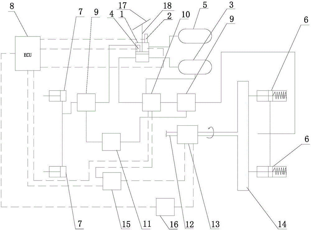
[0017] figure 1 Among them, a high-efficiency energy recovery system for new energy commercial vehicles, including ECU electronic control unit 8, electromagnetic foot valve 1, proportional relay valve 10, front and rear ABS solenoid valves 9, ABS controller 11, generator 13, front axle and rear axle Axle 14, the front axle is provided with a diaphragm compartment 7, the rear axle 14 is connected with a drive shaft 12, the drive shaft 12 is provided with the above-mentioned generator 13, the generator 13 is connected with the storage battery 15, and the generator 13 is controlled by the generator controller 16 is connected with the ECU electronic control unit 8, the rear axle 14 is provided with a spring brake chamber 6, the electromagnetic foot valve 1 is provided with a pedal 17 and a push rod 18 under the pedal 17, the upper air storage tank 5 and the lower air storage tank 3 are respectively It is connected with the air inlet of the upper chamber and the air inlet of the lo...


PUM


Abstract

Disclosed is a new energy commercial vehicle energy efficient recovery system. The new energy commercial vehicle energy efficient recovery system is characterized in that an electric generator is connected with a storage battery, the electric generator is connected with an ECU (electronic control unit) through an electric generator controller, an acceleration sensor and a displacement sensor are arranged on an electromagnet foot valve, the displacement sensor is used to measure the descending position of an ejection rod, the acceleration sensor moves along with the ejection rod, the acceleration sensor is used to measure the descending accelerated speed of a pedal, the acceleration sensor, the displacement sensor, the storage battery and a proportion relay valve are respectively connected with the ECU, a brake pedal work angle of the maximum point braking of the electromagnet foot valve ranges from 11 degrees to 12.5 degrees, and a brake pedal work angle of the maximum semi-braking of the electromagnet foot valve ranges from 19 degrees to 20.5 degrees. The new energy commercial vehicle energy efficient recovery system is obtained by optimizing a new energy commercial vehicle energy efficient recovery system in the prior art, and the optimized new energy commercial vehicle energy efficient recovery system can recover 50% of energy at most when a vehicle brakes, greatly improves charging efficiency, and reduces wear of friction braking on a brake and related components.

Description

technical field [0001] The invention relates to an automobile energy recovery system, in particular to a new energy commercial vehicle braking energy recovery system. Background technique [0002] At present, all new energy vehicles are equipped with a braking energy feedback system. The principle is to recover the potential energy generated by the vehicle's own weight during the braking process and store it in the supercapacitor in the form of electric energy. At present, new energy vehicles are equipped with braking energy feedback systems. The maximum point of the electromagnetic foot valve brakes the brake pedal at a small working angle, resulting in a low energy recovery rate of the braking energy feedback system and low charging efficiency. Due to the inability to intelligently judge the driver's intention, when the driver brakes urgently, the generator will work, affecting the safety performance of new energy vehicles, and the use of friction braking will cause wear a...

Claims


Application Information

Patent Timeline
IPC IPC(8): B60L7/26
Inventor 张建元马靖席力克周闽俊张涛郑小波周根明
Owner ZHEJIANG KELI VEHICLE CONTROL SYST
Learn More