Electrolytic furnace group
An electrolytic furnace and furnace wall technology, applied in the direction of cells, etc., can solve problems such as difficult electrolytic cell temperature, waste of energy, and environmental pollution, and achieve the effects of preventing leakage, improving operating conditions, and protecting the environment
- Summary
- Abstract
- Description
- Claims
- Application Information
AI Technical Summary
Problems solved by technology
Method used
Image
Examples
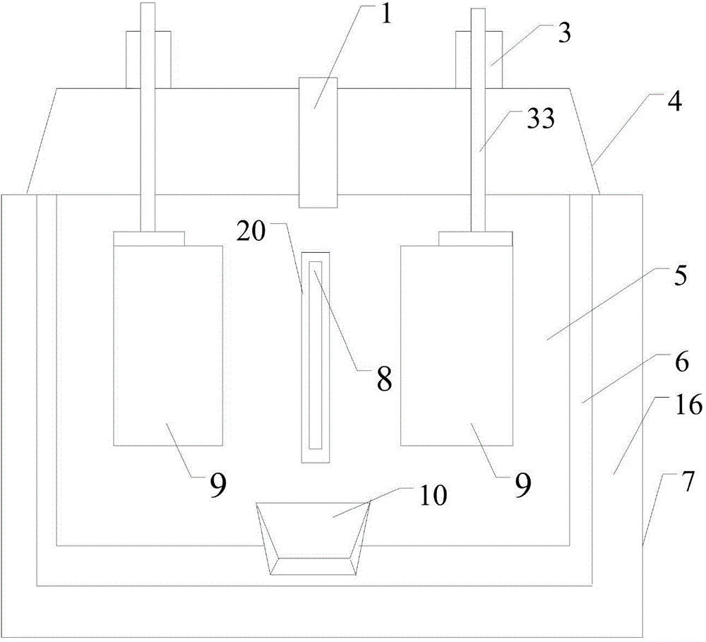
Embodiment 1
[0062] see figure 1 , Figure 7 .
[0063] Electrolytic furnace, including feed pipe 1, adjustment parts 3, sealing cover 4, furnace chamber 5, furnace wall 6, shell 7, cathode 8, graphite anode 9, crucible 10, fixing parts 11, jacketed water cooler 12, insulation layer 16 and anti-seepage insulating part 20. The shell 7 has an insulating layer 16 and a furnace wall 6 made of graphite material from the outside to the inside. The cavity in the furnace wall 6 forms a furnace 5 with an open top, and the top of the furnace 5 is provided with a sealing cover 4 to cover the insulation layer. 16 or more. One cathode 8 and two graphite anodes 9 are arranged in the furnace 5 . The cathode 8 is made of metal plate, one end is vertically suspended in the furnace 5, and the other end is a terminal 81, and the terminal 81 passes through the furnace wall 6 and the shell 7 to the outside of the shell 7; the terminal 81 A part of it is sealed and fixed in the furnace wall 6, the insulati...
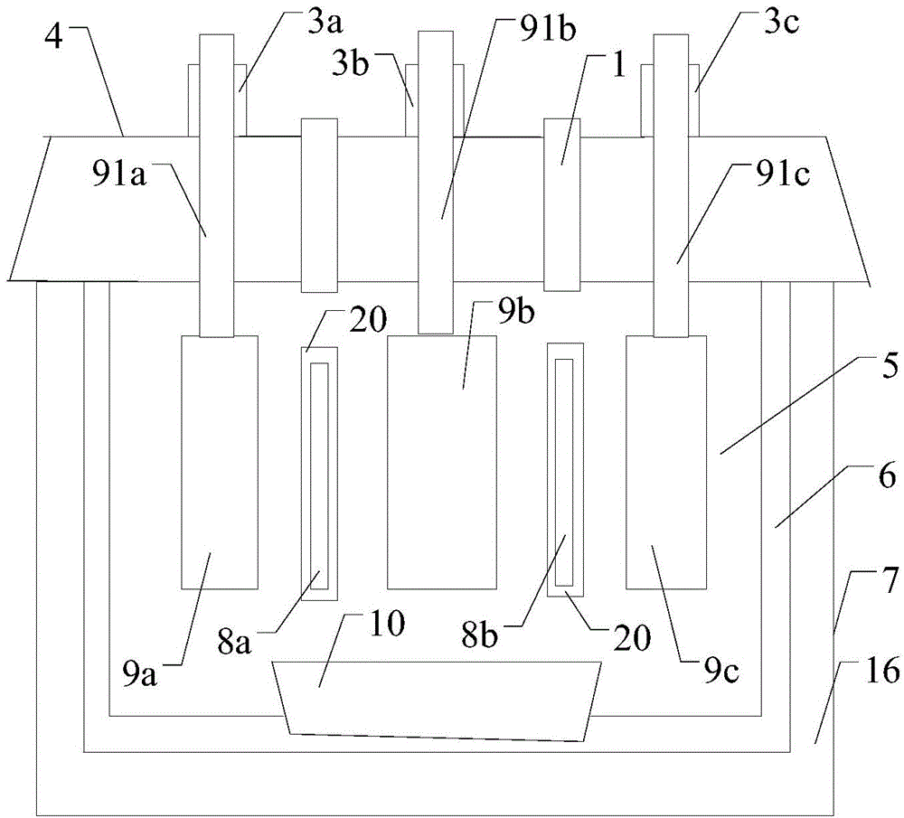
Embodiment 2
[0079] see figure 2 , Figure 7 .
[0080] An electrolytic furnace, including a feed pipe 1, an adjustment component 3, a sealing cover 4, a furnace chamber 5, a furnace wall 6, an outer casing 7, a cathode 8, an anode 9, a crucible 10, a water cooler 12, an insulating layer 16 and an anti-seepage insulating component 20 . There is an insulating layer 16 and a furnace wall 6 inside the shell 7, and the cavity in the furnace wall 6 forms a furnace 5 with an open top. A sealing cover 4 is arranged on the shell 7 to cover the shell 7 therein. The furnace 5 is provided with two cathodes 8a, 8b and three anodes 9a, 9b, 9c. Described each cathode 8 is a metal plate, one end outside the shell 7 to the inner wall of the furnace wall 6 is a terminal 81, and the other end passes through the shell 7 and the insulation layer 16 from the outside of the shell 7, and the furnace wall 6 is vertically suspended on the Inside the furnace 5 , it is sealed and fixed in the furnace wall 6 , ...
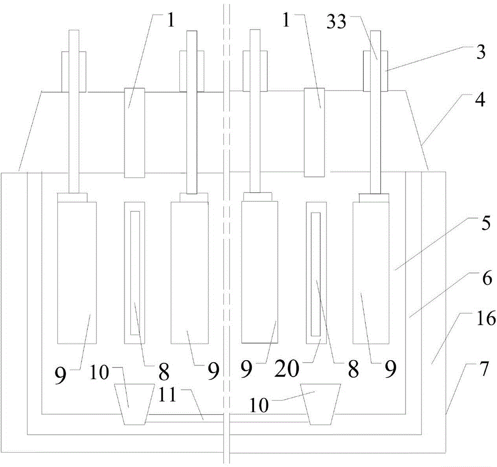
Embodiment 3
[0086] see image 3 , Figure 7 .
[0087] An electrolytic furnace, comprising a feed pipe 1, an adjustment component 3, a sealing cover 4, a furnace chamber 5, a furnace wall 6, a casing 7, a cathode 8, an anode 9, a crucible 10, a channel 11, a jacketed water cooler 12, an insulation layer 16 and Waterproof insulation part 20. There are insulation layer 16 and furnace wall 6 successively in described shell 7, and the cavity in furnace wall 6 forms the hearth 5 of top opening, and the top of hearth 5 is provided with sealing cover 4 and covers on insulation layer 16. Two cathodes 8 and four anodes 9 are arranged in the furnace 5 . One end of each cathode 8 passes through the shell 7 and the insulation layer 16, the furnace wall 6 is vertically suspended in the furnace 5 from the outside of the shell 7, and the other end outside the shell 7 becomes a terminal 81, which is connected to the power supply outside the furnace body. Each cathode 8 is sealed and fixed in the shel...
PUM
 Abstract
Description
Claims
Application Information
 - R&D
- Intellectual Property
- Life Sciences
- Materials
- Tech Scout
- Unparalleled Data Quality
- Higher Quality Content
- 60% Fewer Hallucinations
Browse by: Latest US Patents, China's latest patents, Technical Efficacy Thesaurus, Application Domain, Technology Topic, Popular Technical Reports.
© 2025 PatSnap. All rights reserved.Legal|Privacy policy|Modern Slavery Act Transparency Statement|Sitemap|About US| Contact US: help@patsnap.com


