
Sealing ring for vulcanization pipeline

A sealing ring, integrated technology, applied in the direction of engine sealing, engine components, mechanical equipment, etc., can solve the problems of reducing the cold water section of the vulcanized pipe, failing to achieve cooling, waste, etc., and achieve the effect of improving work efficiency and good sealing.

Inactive Publication Date: 2015-08-05
罗琦俊
View PDF0 Cites 1 Cited by
  • Summary
  • Abstract
  • Description
  • Claims
  • Application Information

AI Technical Summary

Problems solved by technology

When connecting the pull wire and the extruded cable, the sealing of the joint is very important. Once the steam enters the cable, it will seriously affect the quality of the cable and cause serious waste
In order to ensure the tightness of the joint between the pull wire and the extruded cable, some coating and sealing treatment will be done on the joint, and the outer diameter of the wrapped joint is usually larger than the wire diameter of the extruded cable; When the joint passes through the lower closure, if the hole diameter of the conical sealing gasket 6-4 is too small, it may cause the joint to be stuck, resulting in equipment jamming. If the hole diameter of the conical sealing gasket 6-4 is too large, It will seriously affect the tightness of the lower closure, the water level in the return tank will rise, and the water level in the cold water section of the vulcanized pipe will decrease, failing to achieve the purpose of cooling

Method used


Image

  • Sealing ring for vulcanization pipeline
  • Sealing ring for vulcanization pipeline
  • Sealing ring for vulcanization pipeline

Examples


Embodiment 1)

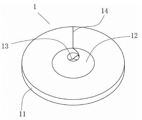
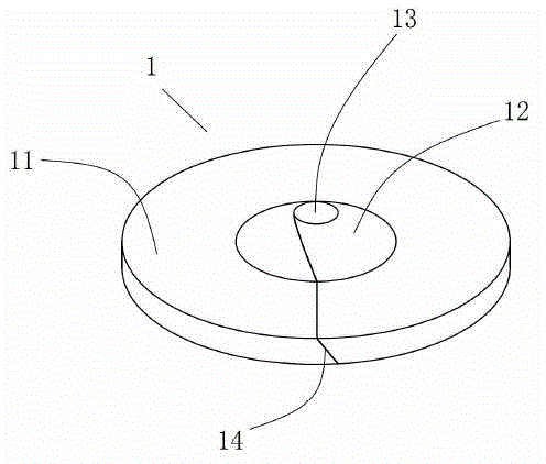
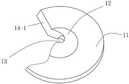
[0051] See figure 1 , figure 2 , Figure 5 and Figure 7 , The sealing ring 1 of the present invention is an integral piece of rubber. Sealing ring 1 includes the main body

[0052] 11 and protrusion 12 . The main body 11 is in the shape of a circular plate as a whole, and the protruding part 12 is in the shape of a conical shell as a whole. Protrusion 12 is located at

[0053] The central position of the main body 11 is connected to the main body 11 from the inside, and is coaxial with the main body 11 , and the axis is the central axis 10 of the sealing ring 1 . The inner cavity of the frustum-shaped protruding portion 12 is used as the wire outlet hole 13 , which is also the central hole of the sealing ring 1 , and the axis of the central hole is also the central axis 10 of the sealing ring 1 .

[0054] See Figure 4 to Figure 7 , the outlet hole 13 includes a first hole section 13-1 and a second hole section coaxially arranged in sequence from top to bottom

...


PUM


Abstract

The invention discloses a sealing ring. The sealing ring is a rubber integrated part and is characterized by comprising a body portion and a protruding portion which are coaxial. The axis is the central axis of the sealing ring, and the body portion is wholly in a circular-ring plate shape; the protruding portion is wholly in a round table shell shape, and the protruding portion is located at the central position of the body portion and is internally connected to the body portion; an inner cavity of the protruding portion in the round table shell shape serves as a line outlet hole, and the line outlet hole serves a central hole of the sealing ring; and the axis of the central hole is the central axis of the sealing ring. The sealing ring is provided with a linear cutting line with the rear portion cut off in the upper right to the lower left direction to serve as an adjusting line; and the front end of the adjusting line is communicated with the line outlet hole, and the rear end of the adjusting line is communicated with external space; and two cutting faces, forming the adjusting line, of the sealing ring are attached, and the included angles alpha between the cutting faces and the central axis of the sealing ring range from 20 degrees to 70 degrees.

Description

technical field [0001] The invention relates to a sealing ring, in particular to a sealing ring used in a lower sealer of a vulcanization pipeline. Background technique [0002] The lower sealer is the device used for sealing the lower end of the vulcanization pipeline of the nitrogen cross-linking unit. Together with the upper sealer, it is [0003] Make the whole pipeline form a closed system, so that the cable can realize continuous vulcanization and cooling process in the pipeline. As we all know, in the continuous vulcanization production process, the line to be extruded needs to be pulled by the pulling line after being extruded, and finally to the take-up reel. When connecting the pull wire and the extruded cable, the sealing of the joint is very important. Once the steam enters the cable, it will seriously affect the quality of the cable and cause serious waste. In order to ensure the tightness of the joint between the pull wire and the extruded cable, some coating...

Claims


Application Information

Patent Timeline
IPC IPC(8): F16J15/02
CPCF16J15/104
Inventor 罗琦俊
Owner 罗琦俊
Learn More