
A 12/6-pole hybrid rotor structure magnetic levitation switched reluctance generator and its control method

A switched reluctance, hybrid rotor technology, applied in synchronous generators and other directions, can solve the problems of the output power density to be improved, the mechanical energy conversion efficiency is low, etc., and achieve high utilization efficiency, strong radial load capacity, and small radial force fluctuations. Effect

Active Publication Date: 2018-06-26
JIANGSU UNIV
View PDF5 Cites 0 Cited by
  • Summary
  • Abstract
  • Description
  • Claims
  • Application Information

AI Technical Summary

Problems solved by technology

Taking a 12 / 8-pole switched reluctance generator as an example, in the one-way conduction mode, only one phase winding inductance is located in the drop zone at the same time, and only 4 poles of the rotor can generate braking torque, the conversion efficiency of mechanical energy is low, and the output power density needs to be improve

Method used


Image

  • A 12/6-pole hybrid rotor structure magnetic levitation switched reluctance generator and its control method
  • A 12/6-pole hybrid rotor structure magnetic levitation switched reluctance generator and its control method
  • A 12/6-pole hybrid rotor structure magnetic levitation switched reluctance generator and its control method

Examples


Embodiment Construction

[0028] The specific implementation manner of the present invention will be further described below in conjunction with the accompanying drawings.

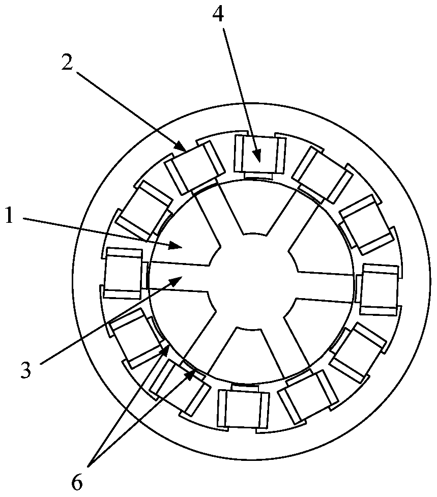
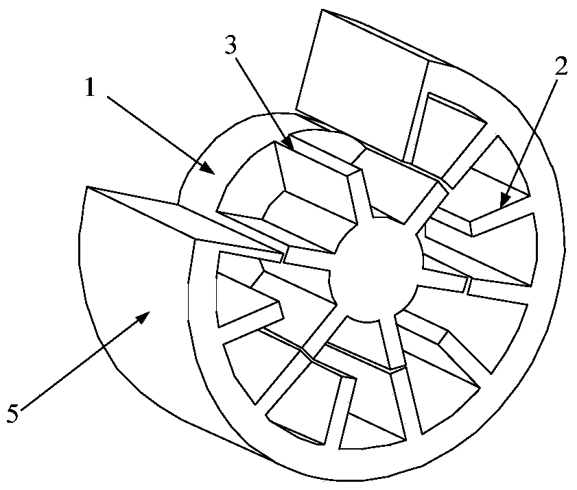
[0029] Such as figure 1 , 2 As shown, the mixed rotor structure magnetic levitation switched reluctance generator of the present invention, the motor core is composed of a salient pole stator, a salient pole rotor and a disc shaft hybrid structure; including a disc 1, a stator salient pole 2, a rotor salient pole 3, Winding 4, stator core 5, air gap 6. The rotor is composed of a disk 1 and a rotor salient pole 3 axially superimposed; the disk 1 provides radial force, and the rotor salient pole 3 provides braking negative torque.

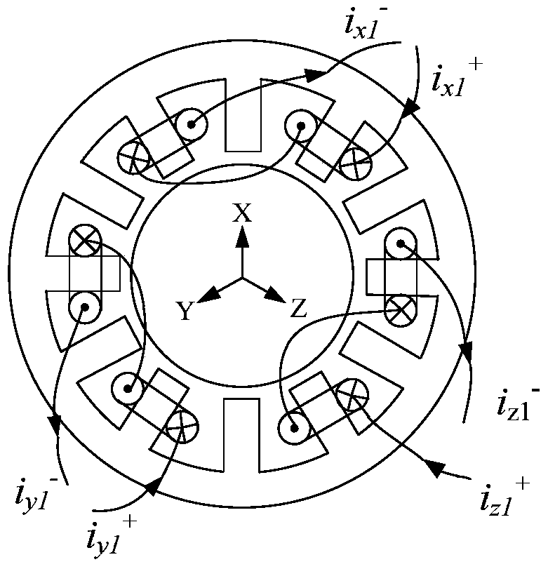
[0030] The hybrid rotor structure magnetic levitation switched reluctance generator of the present invention has 12 salient teeth of the stator and 6 rotor salient teeth of the hybrid structure, and each phase winding is composed of two windings 4 connected in series with an interval of 60°, and each ph...


PUM


Abstract

The invention discloses a 12 / 6-pole hybrid rotor structure magnetic suspension switched reluctance generator and a control method thereof. A stator of the generator has 12 tooth poles, each stator tooth pole is wound by a winding, a rotor is formed by axial superposition of 6 tooth poles and a disc and has no windings. The pole width of salient poles of the generator stator is the same as that of salient poles of the rotor. The structure enables inductance of each phase to have a 1 / 2 cycle to be located in a flat area of the bottom, 1 / 4 to be located in a rising area, and 1 / 4 to be located in a falling area. In power generation operation, only three phases in a mechanical structure which form 120 degrees with one another and whose inductance is located in the flat area and the rising area are conducted, each phase independently controls generation of suspension force and provides excitation for a power generation stage, and the rest three phases located in the inductance falling area generates electricity with follow current. The novel generator integrates a radial magnetic bearing and a switched reluctance motor, rotor pole braking torque is large, generated output is large, influence of suspension phase current on power generation phase current is small, and the radial load capacity is high.

Description

technical field [0001] The invention relates to a magnetic suspension switched reluctance generator with a hybrid rotor structure and a control method thereof, belonging to the field of magnetic suspension switched reluctance generators. Background technique [0002] The magnetic levitation switched reluctance motor combines the magnetic bearing technology with the switched reluctance motor to realize that the magnetic bearing and the switched reluctance motor share a set of windings. Running without bearings. Due to the similarity between the structure of the maglev switched reluctance motor and the switched reluctance motor, following the research on the electric operation of the maglev switched reluctance motor, expanding the power generation operation mode of the maglev switched reluctance motor has become a research hotspot. [0003] The excitation and power generation process of the traditional maglev switched reluctance generator is controlled periodically and time-s...

Claims


Application Information

Patent Timeline
Patent Type & Authority Patents(China)
IPC IPC(8): H02K19/16
Inventor 孙玉坤杨凯
Owner JIANGSU UNIV
Learn More