Low power hid lamp drive circuit

A driving circuit and low-power technology, applied in the field of low-power HID lamp driving circuit, can solve the problems of inconvenient use, unfavorable arc formation and maintenance of HID lamps, difficult lighting of HID lamps, etc.

Active Publication Date: 2019-05-07
QUANZHOU NORMAL UNIV
View PDF5 Cites 0 Cited by
  • Summary
  • Abstract
  • Description
  • Claims
  • Application Information

AI Technical Summary

Problems solved by technology

However, if the low-frequency driving square wave is also used for lighting when starting, it is not conducive to the formation and maintenance of the arc when the HID lamp is started, and the HID lamp is not easy to light up.
[0005] In addition, most of the control methods of existing HID lamps only use wired power switches. When in use, the HID lamps can only be manually adjusted, timed, and switched on and off, which is not very convenient to use.

Method used


Image

  • Low power hid lamp drive circuit
  • Low power hid lamp drive circuit
  • Low power hid lamp drive circuit

Examples


Embodiment Construction

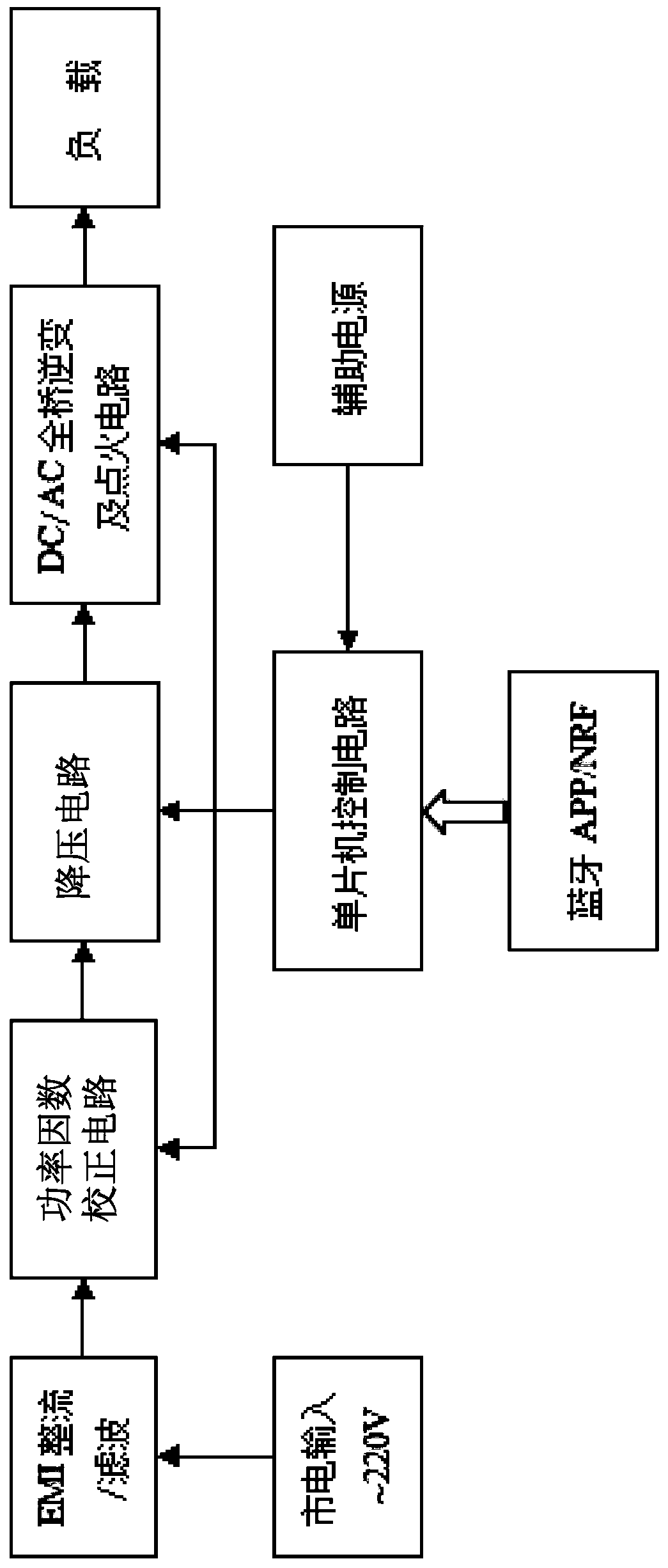
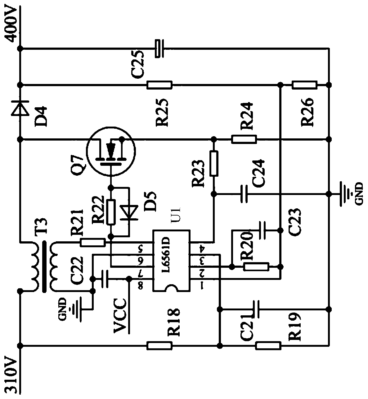
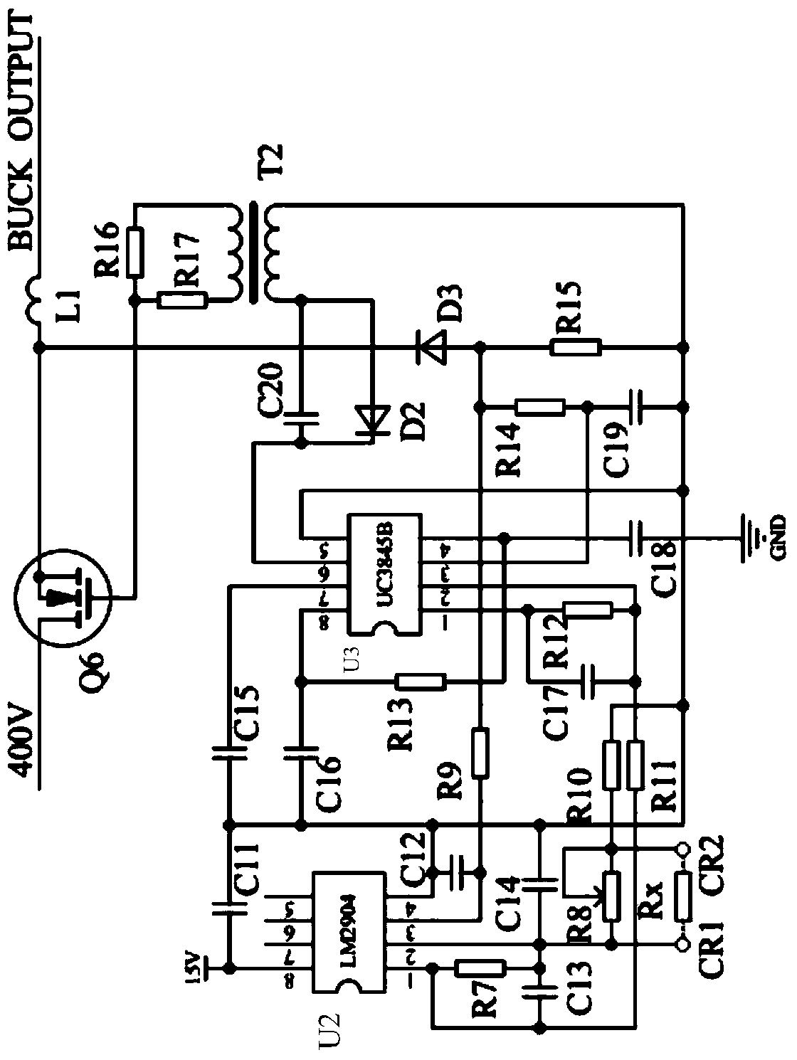
[0026] The low-power HID lamp drive circuit of the present invention, such as figure 1 As shown, it includes EMI rectification / filtering circuit, power factor correction circuit, step-down circuit, DC / AC full-bridge inverter and ignition circuit and single-chip microcomputer control circuit. The input end of the EMI rectification / filtering circuit is connected to the mains input power ~220V, and the output end of the EMI rectification / filtering circuit is connected to the power factor correction circuit, step-down circuit, DC / AC full-bridge inverter and ignition circuit in turn, and the DC / AC full-bridge The output end of the bridge inverter and the ignition circuit is connected to the load, and the output end of the single-chip microcomputer control circuit is respectively connected with the corresponding control ends of the power factor correction circuit, the step-down circuit and the full-bridge inverter and the ignition circuit.

[0027] Electromagnetic Interference (EMI)...


PUM


Abstract

The invention discloses a miniwatt HID lamp drive circuit. A step-down circuit employs a PWM DC-DC circuit, and comprises an operational amplifier, a current control type pulse width modulator, and a first switching tube. The inverted input end of the operational amplifier of the step-down circuit is connected with a reference resistor, and the reference resistor is formed by that an adjustable resistor and a digital control resistor, which are in parallel connection, are in series connection. A feedback signal of a full-bridge output current flows into the non-inverting input end of the operational amplifier, and the feedback input value of the feedback signal is just related to the resistance of the reference resistor. Finally, the output power (lamp power) of the circuit is changed through the control of the resistance of the digital resistor of the reference resistor. A user sends an instruction to a single-chip microcomputer control circuit through an operating part, and the single-chip microcomputer control circuit outputs a control signal to the digital control resistor, so as to control the resistance of the digital control resistor, thereby achieving the manual free change of the output power of an HID lamp and the adjustment of the brightness of the HID lamp.

Description

technical field [0001] The invention relates to an illuminating device driving circuit, in particular to a low-power HID lamp driving circuit. Background technique [0002] Lighting sources are an indispensable element in human life. With the continuous increase of population, people's demand for lighting sources is also increasing. The high-intensity discharge lamp (HID) has good luminous characteristics such as high brightness, high luminous efficiency, no insect trapping, and long life, so it has the value of research. [0003] In the existing low-power HID lamps, the driving circuit generally only uses feedback from the operating current of the HID lamp for constant power control, and it is impossible to freely change the output power of the HID lamp and adjust the brightness of the HID lamp. [0004] In order to effectively avoid the acoustic resonance phenomenon, the existing low-power HID lamps are driven by low-frequency square waves in a steady state, so that the f...

Claims


Application Information

Patent Timeline
Patent Type & Authority Patents(China)
IPC IPC(8): H05B41/36H05B41/38
CPCY02B20/00
Inventor 潘玉灼
Owner QUANZHOU NORMAL UNIV
Why Eureka
Try Eureka