
Vibration energy supply system for cardiac pacemaker

A pacemaker and energy supply technology, which is applied in current collectors, electric vehicles, artificial respiration, etc., can solve the problem of equipment volume, leakage, working temperature, anti-interference, low reliability, and hindering heart beating. and other problems, to achieve the effect of reducing pain and economic burden, improving system reliability, and prolonging battery life.

Active Publication Date: 2015-08-12
UNIV OF SCI & TECH OF CHINA
View PDF5 Cites 5 Cited by
  • Summary
  • Abstract
  • Description
  • Claims
  • Application Information

AI Technical Summary

Problems solved by technology

This method is simple to implement and low in cost, but it is limited by the volume of human implantable devices, so the application prospect is not wide
[0004] At the same time, there is no related method in the prior art that can replenish energy for a cardiac pacemaker without surgical replacement; although there are some reports in the scientific literature that use wireless charging technology to replenish energy for a cardiac pacemaker, they are all in the experimental stage , the volume of the equipment, leakage, operating temperature, anti-interference and other issues have not been well resolved, and the reliability is low
[0005] In addition, although there are some self-powered cardiac pacemaker solutions in the prior art, the power generator is fixed on the surface of the heart, which has the risk of hindering the beating of the heart, and the fixing solution is suture, which is not mature enough

Method used


Image

  • Vibration energy supply system for cardiac pacemaker
  • Vibration energy supply system for cardiac pacemaker
  • Vibration energy supply system for cardiac pacemaker

Examples


Embodiment

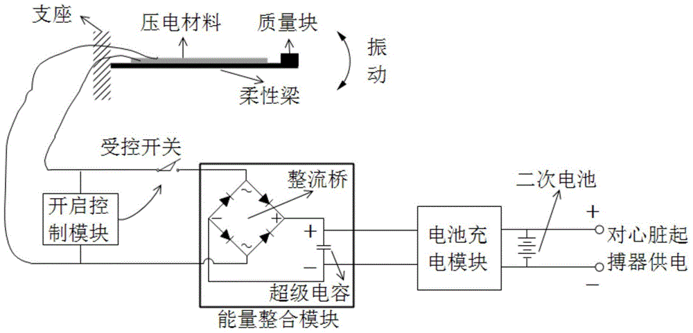
[0033] A vibration energy supply system for a cardiac pacemaker provided by an embodiment of the present invention, such as figure 1 As shown, the system mainly includes: flexible vibration module, energy conversion module, opening control module, energy integration module and battery charging module; where:

[0034] The flexible vibration module is used to convert mechanical vibration into deformation of the flexible vibration module;

[0035] The energy conversion module is used to convert the deformation energy of the flexible vibration module into electrical energy;

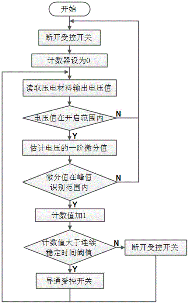
[0036] The opening control module is used to determine the disconnection or conduction of the controlled switch according to the detected electric energy;

[0037] The energy integration module is used to collect and temporarily store electric energy after the controlled switch is turned on;

[0038] The battery charging module is used to charge the electric energy stored in the energy integration module in...


PUM


Abstract

The invention discloses a vibration energy supply system for a cardiac pacemaker, and the system comprises a flexible vibration module, an energy conversion module, a start control module, an energy integration module, and a battery charging module. The flexible vibration module is used for enabling the mechanical vibration to be converted into the deformation of the flexible vibration module. The energy conversion module is used for enabling the energy of the deformation of the flexible vibration module to be converted into electric energy. The start control module is used for determining the on / off of a controlled switch according to the intensity of detected electric energy. The energy integration module is used for collecting and temporarily storing electric energy when the controlled switch is switched on. The battery charging module is used for enabling the electric energy stored by the energy integration module to be conducted to a lithium battery of the cardiac pacemaker. Through the above technical scheme of the invention, the system can achieve the collection and use of vibration energy of a human body, can prolong the service life of the battery of the cardiac pacemaker, reduces the number of times of battery replacement operations, and alleviates the pain of a patient.

Description

technical field [0001] The invention relates to the technical field of energy collection, in particular to a vibration energy supply system for a cardiac pacemaker. Background technique [0002] A pacemaker is an implanted device in the human body. It stimulates the myocardium through pulsed discharge to treat arrhythmia and other diseases. Its energy cannot be replenished from the outside world. Once the energy is exhausted, the pacemaker must be surgically removed and replaced. Many patients need to rely on cardiac pacemakers for life, and frequent surgical replacement will bring physical pain and economic burden to patients. [0003] At present, the country has clear standards for the service life of pacemaker batteries, and the national standard for dual-chamber pacemaker with frequency response (DDDR) is only 5 years. It is the most simple and intuitive way to prolong the life of cardiac pacemaker by expanding the battery capacity. This method is simple to implement a...

Claims


Application Information

Patent Timeline
IPC IPC(8): A61N1/36H02J7/32
Inventor 唐晓鹏陈宗海
Owner UNIV OF SCI & TECH OF CHINA
Learn More