Full-automatic machining tool punching center hole through saw

A center hole, fully automatic technology, used in metal processing mechanical parts, clamping, support and other directions, can solve the problems of inconvenient adjustment when switching between drilling and milling processes, reducing production and processing efficiency, complex equipment structure, etc., to achieve simple structure and cost. Low, improve the degree of automation, the effect of high degree of automation

Inactive Publication Date: 2015-08-12
JUXIN MACHINE TOOL CO LTD
8 Cites 7 Cited by

AI-Extracted Technical Summary

Problems solved by technology

[0004] The above-mentioned main shaft lifting type CNC turning, drilling and milling compound processing machine tool is provided with a vertically arranged spindle box and a tool seat equipped with turning tools, drill bits, and milling cutters on the workbench. Howeve...

Abstract

The invention provides a full-automatic machining tool punching a center hole through a saw, and belongs to the mechanical technical field. The full-automatic machining tool punching the center hole through the saw solves problems that the production cost is high, and the manufacturing procedure is complicated in an existing compound processing machining tool are solved. The full-automatic machining tool punching the center hole through the saw comprises a lathe bed base and a sliding saddle. The sliding saddle is provided with a horizontal guide rail. A left sliding table and a right sliding table are arranged on the horizontal sliding rail. Both the left sliding table and the right sliding table are provided with a power box. Both the left sliding table and the right sliding table are provided with a longitudinal guide rail used for the horizontal movement of the power boxes. Power heads which are horizontally arranged are installed on the power boxes, and vertical guide rails used for the vertical movement of the power heads are arranged on the power boxes. Center drills and saw blades are installed at the ends of the power heads. A first fixture, a second fixture, a third fixture and a fourth fixture are installed at the front end of the lathe bed base, the first fixture and the second fixture are fixed on the lathe bed base, the third fixture and the fourth fixture can move on the lathe bed base, and the feeding mechanism is installed and arranged at the left side of the lathe bed base. The full-automatic machining tool punching the center hole through the saw has the advantages that a compound processing function is possessed, and the automation degree is high.

Application Domain

Work clamping meansOther manufacturing equipments/tools +4

Technology Topic

Drill bitMachine tool +3

Image

  • Full-automatic machining tool punching center hole through saw
  • Full-automatic machining tool punching center hole through saw

Examples

  • Experimental program(1)

Example Embodiment

[0016] The following are specific embodiments of the present invention in conjunction with the accompanying drawings to further describe the technical solutions of the present invention, but the present invention is not limited to these embodiments.
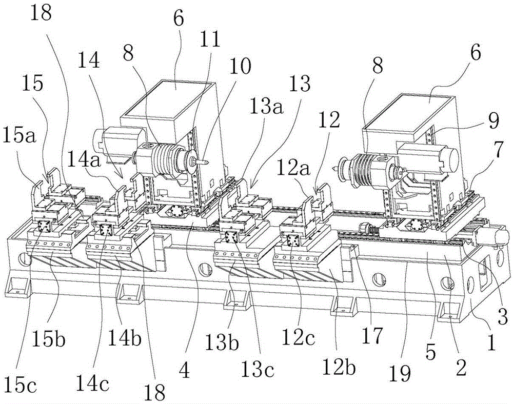
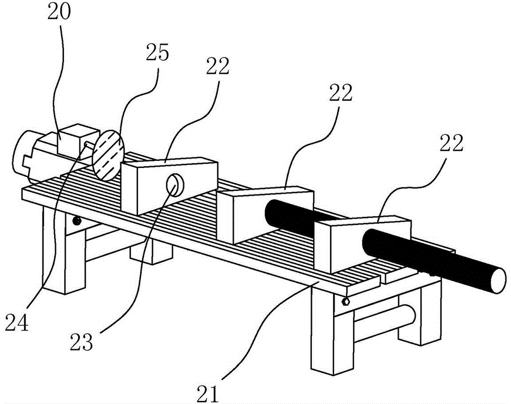
[0017] Such as figure 1 , figure 2 As shown, the fully automatic sawing and centering machine tool includes a bed base 1 and a saddle 2 arranged on the bed base 1. The saddle 2 has two horizontal guides 3 arranged in parallel, and the left The sliding table 4 and the right sliding table 5, the left sliding table 4 and the right sliding table 5 are equipped with a power box 6, and the left sliding table 4 and the right sliding table 5 are equipped with longitudinal guide rails 7 for the power box 6 to move forward and backward. The box 6 is equipped with a horizontally arranged power head 8 and the power box 6 also has a vertical track 9 for the power head 8 to move up and down. The end of the power head 8 is equipped with a center drill bit 10 and a saw blade 11, and a bed base 1 Fixture one 12, fixture two 13, fixture three 14 and fixture four 15 are installed at the front end of the. Fixture one 12 and fixture two 13 are fixed on the bed base 1 and located between the left sliding table 4 and the right sliding table 5. The clamp three 14 and the clamp four 15 are located at the left end of the bed base 1 and the clamp three 14 and the clamp four 15 can move on the bed base 1, and a feeding mechanism 16 is installed on the left side of the bed base 1.
[0018] Such as figure 1 , figure 2 As shown, in this fully automatic sawing and centering machine tool, the fixture one 12 includes a base 12b and a chuck 12a, and an elastic cylinder 12c is arranged between the base 12b and the chuck 12a, and the fixture two 13 includes base two. 13b and the second chuck 13a, and the second elastic cylinder 13c is arranged between the second jig 13 and the second base 13b. Both the first 12b and the second 13b are fixed to the bed base 1 by bolts 17. The three 14 includes the third base 14b and The chuck three 14a and the elastic cylinder three 14c is arranged between the base three 14b and the chuck three 14a, the clamp four 15 includes the base four 15b and the chuck four 15a, and the elastic cylinder four is arranged between the base four 15b and the chuck four 15a. 15c, the upper part of the base three 14b has a sliding rail 18 for the chuck three 14a to move left and right, and the upper part of the base four 15b also has a sliding rail 18 for the chuck four 15a to move left and right.
[0019] Such as figure 1 , figure 2 As shown, in this fully automatic sawing and centering machine tool, the edge of the bed base 1 has a convex edge 19 protruding upward, the base three 14b and the base four 15b are arranged on the convex edge 19, and the base three 14b and the base four 15b It can move left and right on the flange 19.
[0020] Such as figure 1 , figure 2 As shown, in this fully automatic sawing and centering machine tool, the feeding mechanism 16 includes a pushing cylinder 20, a fixing frame 21, and a connecting plate 22 installed on the upper part of the fixing frame 21. The pushing cylinder 20 is arranged at the left end of the fixing frame 21, A through hole 23 for the material to be processed is opened in the middle of the connecting plate 22, and a push plate 25 is installed on the cylinder shaft 24 of the pushing cylinder 20.
[0021] The working principle of the present invention is as follows: in the present invention, after the machine tool starts to run, the power head 8 drives the center drill bit 10 and the saw blade 11 to start working and move to the position to be processed, and the feeding mechanism 16 sends the materials to the fixture three 14 and fixture four. In 15, clamp three 14 and clamp four 15 clamp the material to the specified position, the saw blade 11 on the left end power head 8 cuts off one end of the material, then clamp three 14 and clamp four 15 continue to send the material to clamp two 13 , At this time, clamp four 15 is loosened and then retreat to the original position, clamp three 14 sends the material to clamp one 12, clamp three 14 is loosened and then retreats to the original position, clamp one 12 and clamp two 13 clamp the material and start to enter automatic cutting And the process of punching the center hole.
[0022] The specific embodiments described herein are merely examples to illustrate the spirit of the present invention. Those skilled in the art to which the present invention pertains can make various modifications or additions to the specific embodiments described or use similar alternatives, but they will not deviate from the spirit of the present invention or exceed the definition of the appended claims. Range.
[0023] Although this article uses the bed base 1, the saddle 2, the horizontal guide 3, the left slide 4, the right slide 5, the power box 6, the longitudinal guide 7, the power head 8, the vertical rail 9, the center drill bit 10. , Saw blade 11, clamp one 12, clamp one 12a, base one 12b, elastic cylinder one 12c, clamp two 13, clamp two 13a, base two 13b, elastic cylinder two 13c, clamp three 14, clamp three 14a, Base three 14b, elastic cylinder three 14c, clamp four 15, chuck four 15a, base four 15b, elastic cylinder four 15c, feeding mechanism 16, bolt 17, slide rail 18, flange 19, push cylinder 20, fixing frame 21 , Connecting plate 22, through hole 23, cylinder shaft 24, push plate 25 and other terms, but the possibility of using other terms is not excluded. These terms are used only to describe and explain the essence of the present invention more conveniently; to interpret them as any additional limitation is contrary to the spirit of the present invention.

PUM

no PUM

Description & Claims & Application Information

We can also present the details of the Description, Claims and Application information to help users get a comprehensive understanding of the technical details of the patent, such as background art, summary of invention, brief description of drawings, description of embodiments, and other original content. On the other hand, users can also determine the specific scope of protection of the technology through the list of claims; as well as understand the changes in the life cycle of the technology with the presentation of the patent timeline. Login to view more.

Similar technology patents

System and method for forecasting molten steel components in RH refining process in online manner

InactiveCN103382514AGuaranteed Reasonableness and Accuracyhigh degree of automation
Owner:NORTHEASTERN UNIV +1

Flexible production system for micro die casting fitting grinding detection

ActiveCN110385618AImprove flexible production and management levelhigh degree of automation
Owner:CHONGQING INST OF GREEN & INTELLIGENT TECH CHINESE ACADEMY OF SCI

Plastic bag in-half folding bagging machine

Owner:安徽银生电气设备有限公司

Classification and recommendation of technical efficacy words

Why Eureka
Try Eureka