Crossed slider third axis set mechanism matched with positive-axis mechanism on numerical control turn milling main shaft box moving machine

A technology of cross slider and centering machine, which is applied in the direction of metal processing machinery parts, other manufacturing equipment/tools, large fixed members, etc. It can solve the problems that complex parts cannot be realized, so as to avoid resistance, improve self-precision, and reduce heat generation Effect

Inactive Publication Date: 2015-08-12
NANJING JIANKE MACHINERY
View PDF6 Cites 1 Cited by
  • Summary
  • Abstract
  • Description
  • Claims
  • Application Information

AI Technical Summary

Problems solved by technology

[0005] The technical problem solved by the invention is the problem that the existing rotary milling machi

Method used


Image

  • Crossed slider third axis set mechanism matched with positive-axis mechanism on numerical control turn milling main shaft box moving machine
  • Crossed slider third axis set mechanism matched with positive-axis mechanism on numerical control turn milling main shaft box moving machine
  • Crossed slider third axis set mechanism matched with positive-axis mechanism on numerical control turn milling main shaft box moving machine

Examples


Embodiment 1

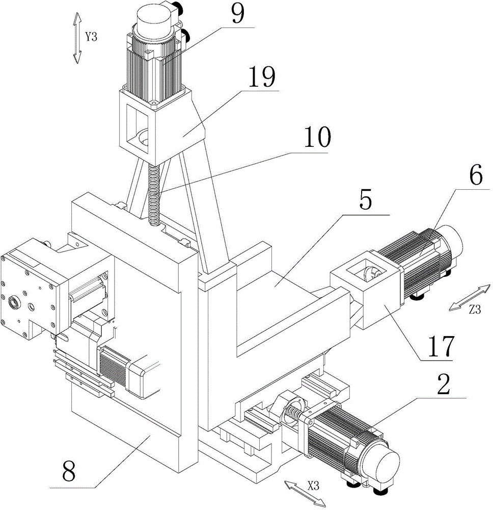
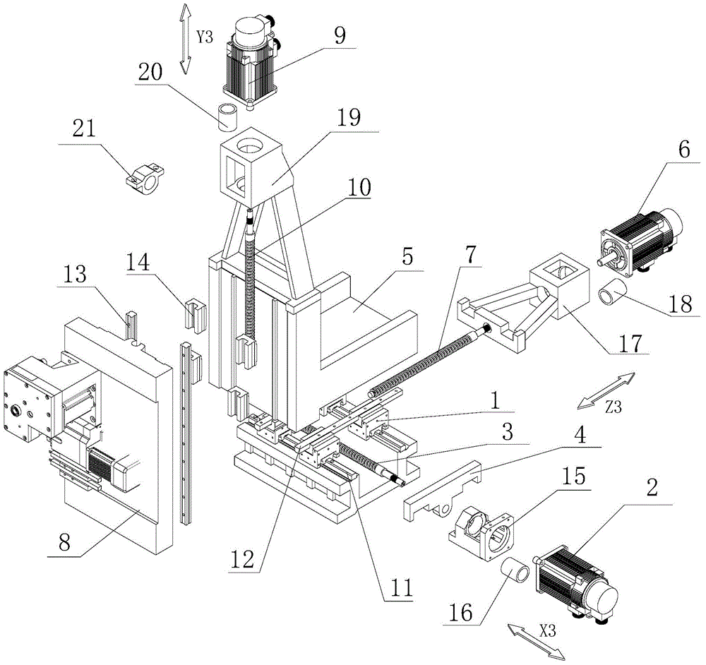
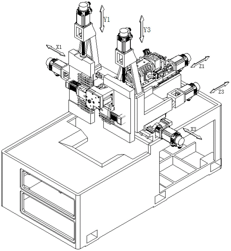
[0048] Such as Figure 1 to Figure 3 The third axis group machine for the turning-milling machine tool with cross slider includes a bed, X3 axis group, Z3 axis group and Y3 axis group arranged on the bed.

[0049] The X3 axis group includes four cross sliders 1 with an integrated structure, X3 axis motor 2, X3 axis screw rod 3, X3 axis coupling 16, two parallel X3 axis rails 11, X3 axis motor seat 15 and X3 axle seat 21. The X3 axis rail 11 is arranged on the bed, the cross slider 1 is arranged on the X3 axis rail 11, two cross sliders 1 are arranged on each X3 axis rail 11, and the bottom of the cross slider 1 is connected to the The X3 axis rail 11 constitutes a sliding pair, and the X3 axis motor base 15 is arranged on the bed (the X3 axis motor base 15 is fixed on the bed by bolts, and can also be integrally manufactured with the bed when manufacturing the bed). A sliding seat 4 is fixed on the cross slider 1 located on the same X3 axis rail 11, and the X3 axis nut is ar...

Embodiment 2

[0057] This embodiment is similar to Embodiment 1, the difference is that the tool mounting seat 8 is a turret, the tool is installed on the turret, and the tool is changed by using the 360-degree rotation of the turret. Other structures are the same as in Embodiment 1, and can be compared for specific implementation. Example 1, which will not be described too much here. At this time, the turret rotates 360°, and the tools at each station of the turret can be changed flexibly to realize the processing of the workpiece. This assembly structure not only saves space, but also can be installed on the turret. Increase the variety and quantity of cutting tools, power heads, etc. to a certain extent, and the disc design is conducive to chip removal when the tool is processing parts, and to a greater extent strengthens the rigidity of the tool when processing parts. Such a structure increases the practical operability of the machine tool and also increases the processing performance o...

Embodiment 3

[0059] Compared with Embodiment 1 in this embodiment, the tool mount 8 is composed of a Y3-axis slide plate and a turret mounted on the Y3-axis slide plate, and the Y3-axis slide plate is slidably mounted on the second Z3-axis slide plate. The Y3-axis screw rod 10 is threadedly connected with the Y3-axis slide plate. Compared with Embodiment 1, this embodiment is that a turret is installed on the Y3-axis slide plate, and a tool is installed on the turret. The rest of the structure is the same as Embodiment 1, and will not be repeated here. At this time, the turret rotates 360°, and the tools at each station of the turret can be changed flexibly to realize the processing of the workpiece. This assembly structure saves space. Not only can various original standard tools be installed on the turret, but Increase the variety and quantity of cutting tools, power heads, etc. to a certain extent, and the disc design is conducive to chip removal when the tool is processing parts, and t...


PUM


Abstract

The invention discloses a crossed slider third axis set mechanism matched with a positive-axis mechanism on a numerical control turn milling main shaft box moving machine. The crossed slider third axis set mechanism is composed of an X3 axis set, a Z3 axis set and a Y3 axis set. The X3 axis set comprises a crossed slider (1), an X3 servo motor (2) and an X3 axis lead screw (3). The Z3 axis set comprises an L-shaped Z3 axis sliding plate (5), a Z3 servo motor (6) and a Z3 axis lead screw (7). The Y3 axis set comprises a cutter installing base (8), a Y3 axis servo motor (9) and a Y3 axis lead screw (10). The crossed slider third axis set mechanism has the advantage that the problem that complicated parts cannot be machined and formed at a time through an existing main shaft box moving type turn milling machine tool, and efficiency is low is solved.

Description

technical field [0001] The invention relates to a third axis group mechanism of a cross slider matched with a positive axis mechanism on a numerically controlled turning, milling, and centering machine. Background technique [0002] In the existing centering machine market, there has been research on the technology of machine tool motion axes, and the most widely used one is the three-axis with positive axis structure consisting of X1 axis group, Y1 axis group, and Z1 axis group. Swivel type turning and milling machine; or, when the sub-axis structure is added with Z2 axis group, it can be combined with the positive axis structure to form a four-axis swivel type turning and milling machine tool; or, when the sub-axis is composed of X2 axis group and Z2 axis group The sub-axis structure is combined with the positive axis structure to form a five-axis center-type turning and milling machine tool; or, when the sub-axis structure composed of X2 axis group, Z2 axis group, and Y2 ...

Claims


Application Information

Patent Timeline
IPC IPC(8): B23Q1/62B23Q5/40B23P23/02
CPCB23P23/02B23Q1/62B23Q5/40
Inventor 王建飞
Owner NANJING JIANKE MACHINERY
Why Eureka
Try Eureka