

Conveying device
A conveying device and conveying channel technology, applied in conveyors, mechanical conveyors, transportation and packaging, etc., can solve the problems of low feeding efficiency and rising production costs, and achieve compact structure, reduce production costs, and improve feeding efficiency. Effect
- Summary
- Abstract
- Description
- Claims
- Application Information
AI Technical Summary
Problems solved by technology
Method used
Image

Examples
Embodiment 1
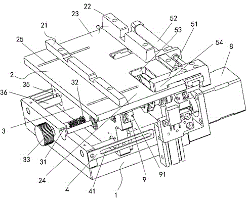
[0045] This embodiment provides a delivery device, such as figure 1 As shown, the installation seat 1 is included, and the installation seat 1 is composed of a bottom plate 10, a vertical plate 11 and a fixed plate 12 fixedly arranged on the bottom plate 10 and extending vertically upward; the conveying device also includes a bearing fixed on the vertical plate 11 Seat 2, the bearing seat 2 and the base plate 10, vertical plate 11 and fixed plate 12 of the mounting seat 1 together form an installation space; the upper surface of the bearing seat 2 is a horizontal bearing surface, and the horizontal bearing surface is provided with first baffles parallel to each other 21 and the second baffle plate 22, the first baffle plate 21, the second baffle plate 22 and the above-mentioned horizontal bearing surface jointly form a transport channel for receiving and transporting the LED chip holder, and the transport channel has a first opening 23 opposite along the length direction and t...
Embodiment 2
[0072] This embodiment provides a conveying device, which is a deformation based on Embodiment 1. In this embodiment, the adjustment structure is different from that in Embodiment 1. Specifically, the adjustment structure includes an adjustment plate 3, fixed A fixed structure connecting the first baffle plate 21 and the adjusting plate 3, at least one guide rail arranged on the bottom plate 10 of the mounting seat 1 and extending along the width direction of the conveying channel, and used to push the adjusting plate 3 back and forth along the guide rail A moving power device. Here, the power device can be an air cylinder, a hydraulic cylinder, or other mechanical propulsion methods.
[0073] When using the adjustment structure to adjust, the power device is used to push / pull the adjustment plate 3 to move back and forth along the guide rail provided on the bottom plate 10, thereby driving the first baffle plate 21 to approach / away from the second baffle plate 22, thereby chan...
Embodiment 3
[0075] This embodiment provides a conveying device, which is a deformation on the basis of the conveying device described in Embodiment 1 or 2, the difference is that an adjusting plate 3 is added in the installation space formed by the mounting seat 1 and the bearing seat 2 , the upper part of the adjusting plate 3 is fixedly connected with the second baffle plate 22 through a fixed structure, and an adjusting member is provided on the vertical plate 11 for pushing and pulling the adjusting plate 3 to move along the width direction of the conveying channel. The adjusting member and fixing structure in this embodiment are the same as those in Embodiment 1.
[0076] Two adjustment plates 3 are respectively connected to the first baffle plate 21 and the second baffle plate 22 through a fixed structure, and two adjustment members are respectively used to drive the two adjustment plates 3 to drive the first baffle plate 21 and the second baffle plate 22 respectively. The movement ...
PUM
 Abstract
Description
Claims
Application Information