Power transmission tower

A technology for transmission towers and tower bodies, applied in the field of self-supporting transmission towers, which can solve the problems of poor bearing performance, inconvenient construction, and high cost of transmission towers, and achieve the effects of increasing bearing capacity, reducing construction costs, and improving pressure capacity

Inactive Publication Date: 2015-08-12
CHINA ELECTRIC POWER RES INST +1
View PDF6 Cites 1 Cited by
  • Summary
  • Abstract
  • Description
  • Claims
  • Application Information

AI Technical Summary

Problems solved by technology

[0005] The above-mentioned problems to be solved are realized by the following technical solutions: provide a transmission tower to solve the shortcomings of existing transmission towers such as poor bearing performance, high cost, large land occupation, and inconvenient construction

Method used


Image

  • Power transmission tower
  • Power transmission tower
  • Power transmission tower

Examples


Embodiment 1

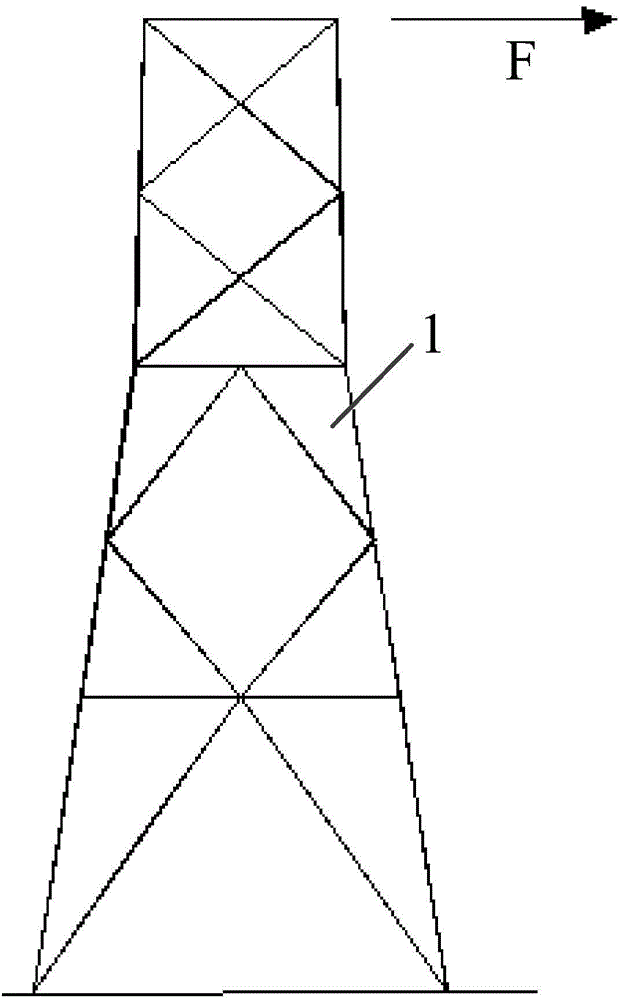
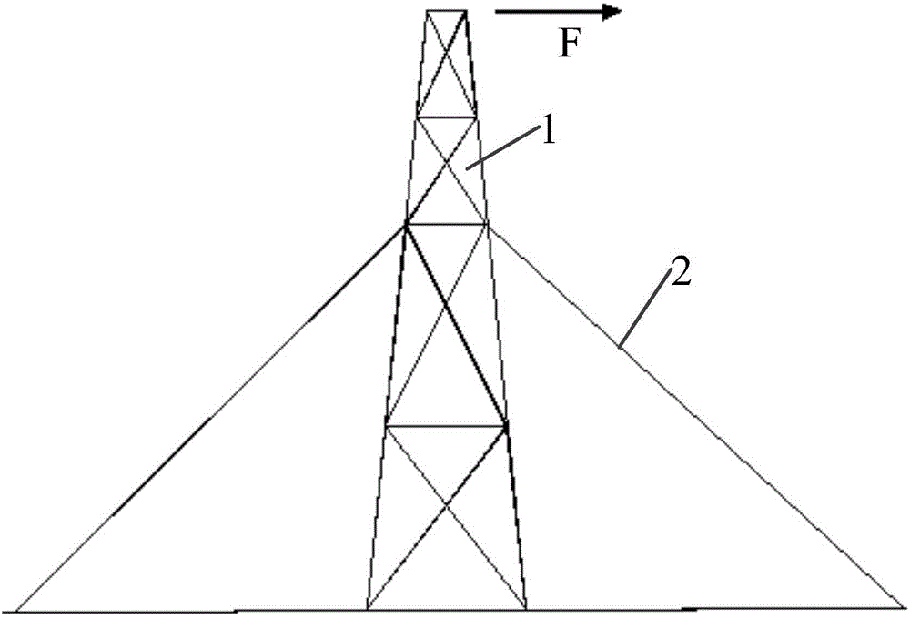
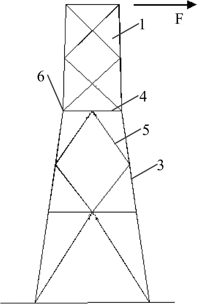
[0034] Such as image 3 As shown, a power transmission tower includes a vertically arranged tower body 1 and a cross arm arranged horizontally on the tower body. The tower body 1 is a frame structure formed by interlacing main materials 3, horizontal materials 4 and oblique materials 5. The connection point between the main material 3 and the cross material 4 is a node 6 .

[0035] The four main materials 3 are distributed at 90 degrees on the horizontal plane, and the nodes 6 form a hexahedron whose upper and lower sides are rectangular.

[0036] Node 6 forms a square diaphragm on the same plane.

[0037] The number of transverse partitions is two, and the transmission tower is divided into three floors.

[0038] The two ends of the oblique material 5 are respectively connected with the adjacent main material 3 and the horizontal material 4 to form a diagonal bracing surface;

[0039] The main material 3 and the horizontal material 4 are steel pipes filled with concrete. ...


PUM


Abstract

The invention relates to a power transmission tower. The power transmission tower comprises a tower body and a cross arm, wherein the tower body is longitudinally arranged; the cross arm is horizontally arranged on the tower body; the tower body comprises multiple main materials, cross materials and diagonal materials; the main materials, the cross materials and the diagonal materials are connected to form a framework structure in a staggered way; multiple nodes are formed on the main materials. The power transmission tower provided by the invention not only is capable of completing the work of replacing damaged main materials of an iron tower, but also has the advantages that the construction is simple, and the transportation is convenient and is not limited by places.

Description

technical field [0001] The invention relates to power transmission equipment, in particular to a self-supporting power transmission tower. Background technique [0002] In the process of long-distance transmission of electric energy, it often needs to pass through some quite remote areas, such as some remote mountainous areas with extremely inconvenient transportation. For electric energy transmission in these areas, it is often necessary to erect transmission towers. [0003] Existing transmission towers can be classified as figure 1 The self-supporting transmission tower shown and the figure 2 Guyed tower shown. At present, self-supporting steel pipe transmission towers are the most widely used, such as figure 1 shown. With the increase of power transmission capacity, the load and height of the transmission tower continue to increase. When its height exceeds 100 meters, the transmission tower will involve problems: (1) Increasing the diameter-thickness ratio of the ma...

Claims


Application Information

Patent Timeline
IPC IPC(8): E04H12/16
Inventor 刘海锋韩军科杨靖波王飞王旭明
Owner CHINA ELECTRIC POWER RES INST
Why Eureka
Try Eureka