Concrete filled steel tube roadside support system used for large-section gob-side entry retaining and support method thereof

A technology of concrete filled steel tube and roadside support, which is used in earth-moving drilling, wellbore lining, tunnel lining, etc., can solve the damage and instability of roadside support structure, the decline of the bearing capacity of roadside filling walls, and the bending deformation of single hydraulic props. And other issues

Inactive Publication Date: 2015-08-12
CHINA UNIV OF MINING & TECH (BEIJING)
View PDF5 Cites 5 Cited by
  • Summary
  • Abstract
  • Description
  • Claims
  • Application Information

AI Technical Summary

Problems solved by technology

Even if the way of erecting wooden point columns and single hydraulic props in the roadway cannot effectively prevent large-area fracturing chips on the side of the filling wall beside the roadway, the wooden point columns are split or broken, and the single hydraulic props are seriously bent and deformed, which leads to The load-carrying capacity of the filling wall at the side of the roadway is reduced, and it is easy to induce the damage and instability of the roadside support structure, so that some mines do not achieve the expected effect when applying the technology of large-section gob-side entry retention, or even fail to retain the entryway, thus limiting the gob-side entry retention Technology is more widely promoted and applied in our country

Method used


Image

  • Concrete filled steel tube roadside support system used for large-section gob-side entry retaining and support method thereof
  • Concrete filled steel tube roadside support system used for large-section gob-side entry retaining and support method thereof
  • Concrete filled steel tube roadside support system used for large-section gob-side entry retaining and support method thereof

Examples


Embodiment Construction

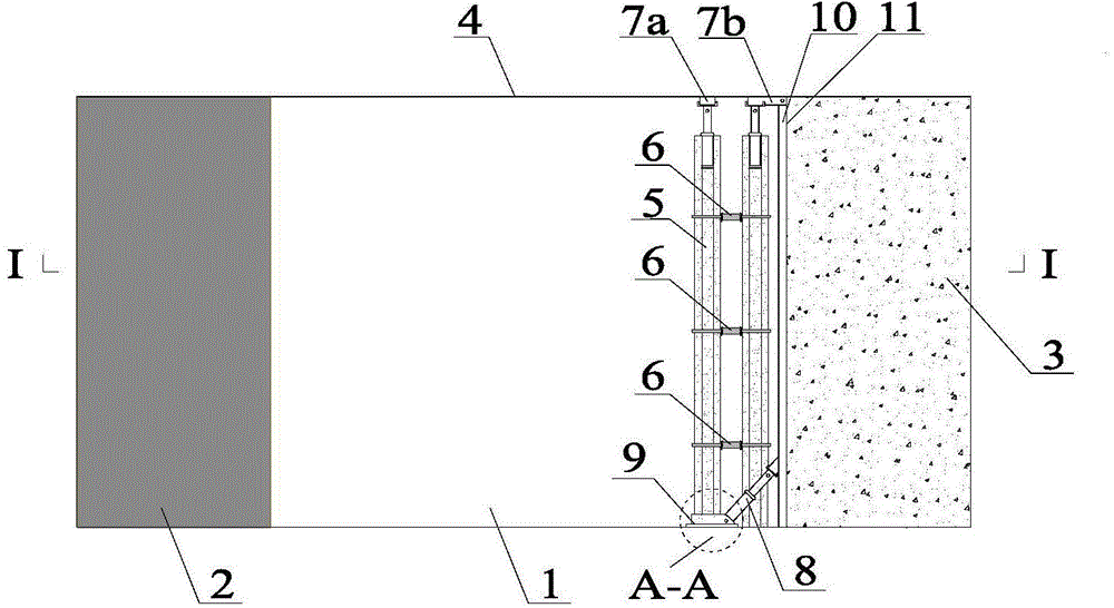
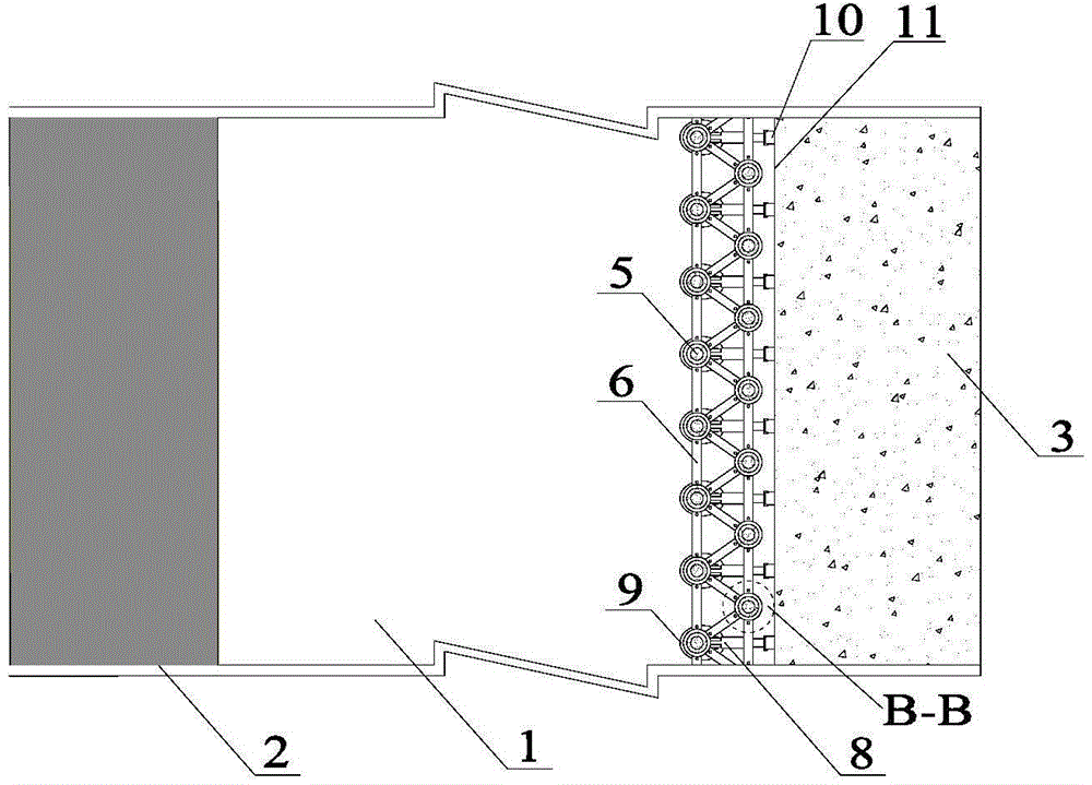
[0040] according to figure 1 - Figure 7 The concrete-filled steel pipe roadside support system of the present invention mainly includes Π-shaped steel beams 7a, 7b close to the top plate 4, the concrete-filled steel pipe column 5 supporting the Π-shaped steel beam on the top plate, the elliptical ring base 9 set on the lower part of the steel-filled steel tube concrete column 5, and The elliptical ring base 9 is an inclined hydraulic jack 8 of the articulated fulcrum, and the end of the inclined hydraulic jack 8 is supported on the vertical Π-shaped steel beam 10 and the metal mesh 11 filling the surface of the wall body 3 .

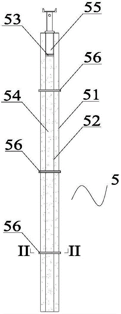
[0041] The concrete-filled steel pipe column 5 includes an 8-inch steel pipe 51, a 5-inch steel pipe 52, a rubber stopper 53, filled concrete 54, a vertical hydraulic jack 55, and a ring pipe clip 56.

[0042] Among them, the 8-inch steel pipe 51 and the 5-inch steel pipe 52 have the same length, the 5-inch steel pipe 52 is set in the 8-inch steel pipe...


PUM


Abstract

The invention provides a concrete filled steel tube roadside support system used for large-section gob-side entry retaining and a support method thereof. The system comprises Pi-type steel beams which are closely clung to a top plate, concrete filled steel tube stand columns which support the Pi-type steel beams of the top plate, elliptical ring bases which sleeve the lower parts of the concrete filled steel tube stand columns, and inclined hydraulic jacks with the elliptical ring bases acting as hinged pivots, wherein the end heads of the inclined hydraulic jacks support the Pi-type steel beams and metal meshes of the surface of the filling wall. A truss structure formed by the concrete filled steel tube stand columns has the main support effect on the top plate and controls subsidence and deformation of the top plate in cooperation with the filling wall. Moderate underframe sinking and pressure releasing can be performed by the concrete filled steel tube stand columns in the process so that stability of the concrete filled steel tube stand columns in a vertical direction can be increased, and then the hydraulic jacks, which are arranged in an inclined way with the elliptical ring bases acting as the hinged pivots, can provide relatively high acting force to support the Pi-type steel beams and the metal meshes of the surface of the filling wall.

Description

technical field [0001] The invention belongs to the technical field of coal mine roadway support, and in particular relates to a steel pipe concrete roadside support system and a support method for large-section gob-side entry retention. Background technique [0002] Gobside retaining refers to retaining the mining roadway behind the mined working face along the edge of the goaf in a certain way, as the mining roadway of the next working face. The gob-side retaining can not only cancel the section protection coal pillars, improve the recovery rate of coal resources, and relieve the tension of mining replacement, but also realize the "Y" ventilation of the working face, fundamentally solve the problem of gas over-limit and the upper corner of the upper working face. Corner Gas Accumulation Conundrum. So far, my country has done a lot of work on the theory and technology research of gob-side entry retention. The technology of gob-side entry retention in the thin and medium-th...

Claims


Application Information

Patent Timeline
Patent Type & Authority Applications(China)
IPC IPC(8): E21D11/00
CPCE21D11/00
Inventor 谢生荣孙运江何尚森谢国强杨军辉
Owner CHINA UNIV OF MINING & TECH (BEIJING)
Why Eureka
Try Eureka