Image sequence and evaluation method and system for structured illumination microscopy

A pattern, space pattern technology, applied in the field of microscope system, can solve the problem of partial tilt, no provision, different height and reflectivity, etc.

Active Publication Date: 2015-08-12
MITUTOYO CORP
View PDF7 Cites 2 Cited by
  • Summary
  • Abstract
  • Description
  • Claims
  • Application Information

AI Technical Summary

Problems solved by technology

[0005] In the prior art, no solution is provided for creating a 3D height map of a specimen with excellent Z resolution and height ind

Method used


Image

  • Image sequence and evaluation method and system for structured illumination microscopy
  • Image sequence and evaluation method and system for structured illumination microscopy
  • Image sequence and evaluation method and system for structured illumination microscopy

Examples


Embodiment Construction

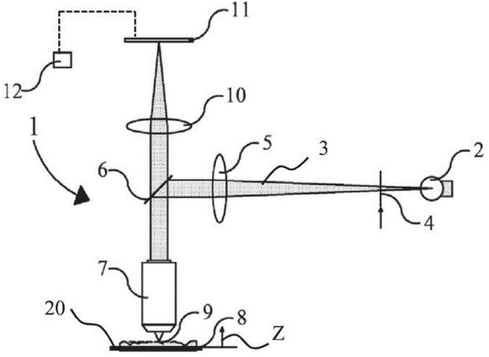
[0059] figure 1 An apparatus 1 for forming a three-dimensional (3D) height map of a specimen 8 is shown. The device 1 comprises a light source 2 constructed and arranged to generate a light beam 3 . In the path of the light beam 3 a spatial light modulator 4, a lens 5 and a beam splitter 6 are arranged. The device 1 also comprises an objective lens 7 adapted to receive and direct the beam of light 3, and a support 20 for carrying a specimen 8 whose upper surface 9 is to be determined with a height map. The device 1 is also equipped with a second lens 10, and a two-dimensional photodetector 11 (such as a camera) comprising an array of photodetector elements, each photodetector element being adapted to receive incident light of the light beam 3 The intensity is transformed into a signal. The signal is sent to a processing unit 12, preferably formed by a computer or computer system programmed to perform control of the device 1 and processing of signal data to provide said hei...


PUM


Abstract

In a method and apparatus for determining the height of a plurality of spatial positions on a surface of a specimen, a light beam is projected on the surface. The light beam has a sinusoidal spatial pattern in at least two directions perpendicular to an optical axis of the light beam, and which is moved to different spatial pattern positions. The surface is scanned along said optical axis in different scanning positions. A fixed relationship between a moving distance between subsequent spatial pattern positions, and a scanning distance between subsequent scanning positions exists. The light reflected by the surface is detected in scanning positions with the spatial pattern having corresponding spatial pattern positions. From the detected light for each spatial position of the surface, an envelope curve of intensity values corresponding to scanning positions is determined. A maximum of the envelope curve and its corresponding scanning position being representative of the height of the spatial position of the surface is selected. The spatial pattern is moved in a sequence of 2n steps (n > 2) in a first and a second spatial direction over a distance of 1/4 and 1/n pattern wavelength, respectively.

Description

technical field [0001] The present invention relates to the field of microscopy systems, and more particularly, to a method and system for structured illumination microscopy. In particular, the present invention relates to an improved method and system for providing a 3D height map of a specimen. Background technique [0002] EP 2 327 956 A1 discloses an optical sensor for determining the range (distance) of individual features of a three-dimensional structure. The sensor has a light source organized into a spatially modulated periodic pattern for illuminating the specimen. An image of the projected pattern is detected using an array of detector elements. While moving the specimen past the focal position, when the spatially periodic light pattern is moved in a direction parallel to the direction in which the periodic pattern is periodic and perpendicular to the optical axis of the optical sensor, the pattern modulates in at least three spaces change in phase. Analyzing t...

Claims


Application Information

Patent Timeline
IPC IPC(8): G01B11/06G01B11/25
CPCG01B11/2527G01B2210/54G02B21/364G01B11/0608G01B11/2513
Inventor H.海特杰马F.德努伊杰L.雷德拉斯基
Owner MITUTOYO CORP
Why Eureka
Try Eureka