Recognition method of mine microseismic and blasting signals based on waveform slope before and after the peak

A signal identification and waveform technology, applied in the field of mine microseismic and blasting signal identification, can solve problems such as the large influence of the waveform start-up slope, the complex on-site production environment, and the inclusion of microseismic information in blasting data.

Active Publication Date: 2017-04-05
CENT SOUTH UNIV
View PDF3 Cites 2 Cited by
  • Summary
  • Abstract
  • Description
  • Claims
  • Application Information

AI Technical Summary

Problems solved by technology

At present, when microseismic monitoring systems are used at home and abroad to monitor the stability of rock mass, they are not recognized by the site due to more or less problems. There are many and complicated, and the impact of blasting is large, resulting in a large amount of blasting data and effective microseismic information mixed together, it is difficult to accurately identify, so that it is difficult to provide intuitive monitoring data for on-site production services, and the traditional manual imprecise Waveform identification and processing can easily lead to serious errors in the rapid calibration of microseismic events and the prediction of the spatial distribution of microseismic events
[0004] The patent application (Application No. 201410556890.4) involving the identification of microseismic events and blasting events provides a mine microseismic and blasting identification method based on the characteristics of waveform vibration. This method has high recognition accuracy, but when the background noise is large, The first peak point is not easy to pick, and the waveform start-up slope is greatly affected by noise, especially when the amplitude of the noise is higher than the first peak value of the original signal, the recognition result will depend more on the start-up slope of the noise signal than the original signal. The signal waveform starts to oscillate, and the recognition result is inaccurate

Method used


Image

  • Recognition method of mine microseismic and blasting signals based on waveform slope before and after the peak
  • Recognition method of mine microseismic and blasting signals based on waveform slope before and after the peak
  • Recognition method of mine microseismic and blasting signals based on waveform slope before and after the peak

Examples


Embodiment 1

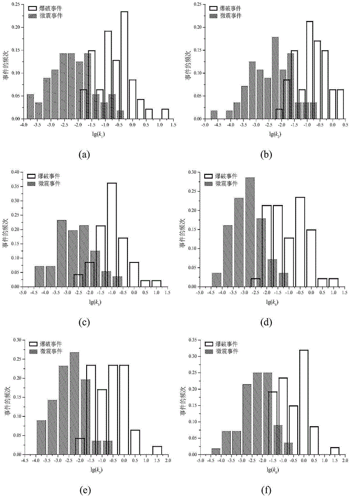
[0078] The mine microseismic and blasting signal identification method based on the waveform slope before and after the peak value of the present embodiment takes N=M=100, and its steps are as follows:

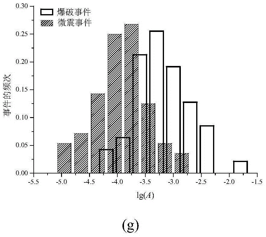
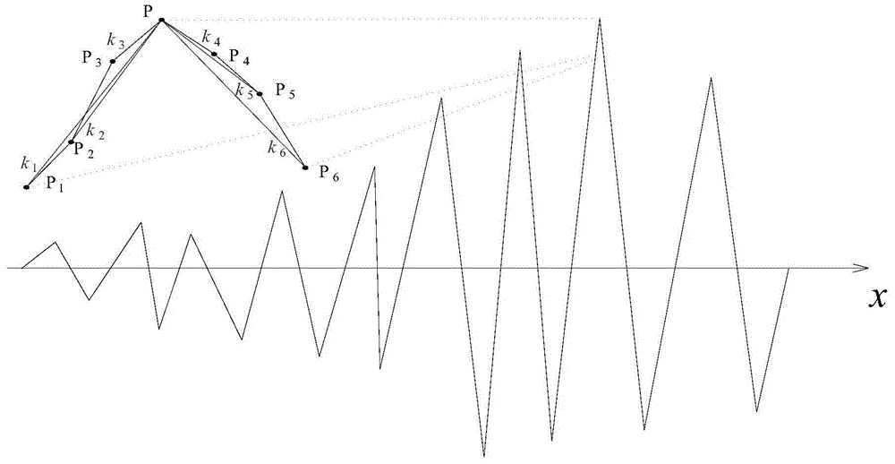
[0079] 1) Select 100 microseismic events and 100 blasting events that have been accurately identified, and the waveform of one microseismic event is as follows image 3 As shown, the waveform of a blasting event is as Figure 4 shown.

[0080] 2) image 3Among them, the maximum peak point of the microseismic event is P(0.3305, -7.36198E-05), so A=7.36198E-05, three sampling points before and after the maximum peak point are selected sequentially in time order, P1 (0.33000, -7.2542E-05), P2 (0.33017, -7.31802E-05), P3 (0.33033, -7.35475E-05), P4 (0.33067, -7.34391E-05), P5 (0.33083, -7.2548E-05) and P6 (0.331, -7.1687E-05). Figure 4 , the maximum peak point of the blasting event is P(0.25433, 0.000208829), so A=0.000208829, three sampling points before and after the maximu...


PUM


Abstract

The invention discloses a mine slight shock and blasting signal identification method based on waveform slope before and after a peak value. The method comprises: step 1, acquiring a linear identification equation: based on N times of slight shock events and M times of blasting events, obtaining a linear identification equation with logarithm of A, logarithm of k1, logarithm of k2, logarithm of k3, logarithm of k4, logarithm of k5, and logarithm of k6 as characteristic parameters, the linear identification equation being Y=a1* lg(k1)+a2*lg(k2)+a3*lg(k3)+a4*lg(k4)+a5*lg(k5)+a6*lg(k6)+b*lg(A)+c; step 2, calculating a distinguishing threshold value Yd; step 3, based on the linear identification equation and the distinguishing threshold value Yd, identifying a to-be-identified event; and calculating a distinguishing value Y of the to-be-identified event, if Y<=Yd, the to-be-identified event being a slight shock event, and if not, the to-be-identified event being a blasting event. The method is low in calculated amount, and identification results are not influenced by signal noise, and the method is high in accuracy.

Description

technical field [0001] The invention relates to a mine microseismic and blasting signal identification method, in particular to a mine microseismic and blasting signal identification method based on the slope of the waveform before and after the peak value. Background technique [0002] Microseismic monitoring is a geophysical technique that monitors subsurface conditions by analyzing microseismic events generated by production activities. Since this technology does not directly measure the basic mechanical parameters such as stress and strain of the monitored rock mass, but determines its stability under stress and deformation through the location of the microseismic source, compared with the traditional displacement and stress monitoring method, microseismic Monitoring technology can know the distribution and evolution process of microcracks inside the rock mass and reflect the deformation or displacement of the rock mass in the adjacent area. In recent years, this techno...

Claims


Application Information

Patent Timeline
Patent Type & Authority Patents(China)
IPC IPC(8): G01V1/28
Inventor 马举赵国彦董陇军李夕兵周子龙
Owner CENT SOUTH UNIV
Why Eureka
Try Eureka