Broadband capacitive coupling laminated GNSS antenna

A technology of capacitive coupling and antenna, which is applied in the field of satellite antenna, can solve the problem that the antenna does not have antenna bandwidth, etc., and achieve the effect of high stability and improved radiation performance

Inactive Publication Date: 2015-08-12
遵义市华颖监测技术有限公司
View PDF2 Cites 13 Cited by
  • Summary
  • Abstract
  • Description
  • Claims
  • Application Information

AI Technical Summary

Problems solved by technology

[0009] In view of the above-mentioned deficiencies in the prior art, the object of the present invention is to provide a broadband capacitive coupling stacked GNSS antenna, which aims to solv...

Method used


Image

  • Broadband capacitive coupling laminated GNSS antenna
  • Broadband capacitive coupling laminated GNSS antenna
  • Broadband capacitive coupling laminated GNSS antenna

Examples


Embodiment Construction

[0027] The present invention provides a broadband capacitively coupled laminated GNSS antenna. In order to make the objectives, technical solutions and effects of the present invention clearer and clearer, the present invention will be described in further detail below. It should be understood that the specific embodiments described here are only used to explain the present invention, but not to limit the present invention.

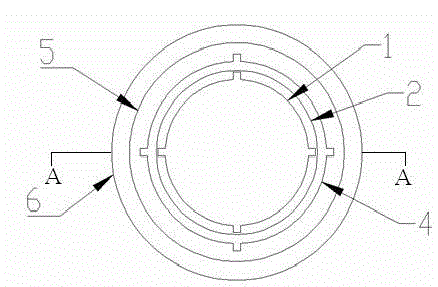
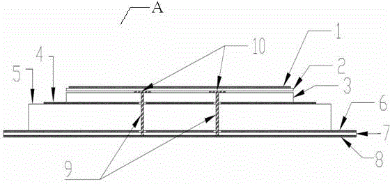
[0028] See Figure 1 to Figure 3 As shown in the figure, the present invention provides a broadband capacitively coupled laminated GNSS antenna, wherein the antenna is sequentially arranged with a first dielectric layer 2, a second dielectric layer 3, a third dielectric layer 5 and a PCB board from top to bottom. 7; Wherein, the upper surface of the first dielectric layer 2 is connected to an upper radiation patch 1, and the lower surface of the first dielectric layer 2 is connected to the upper surface of the second dielectric layer 3 through a small disc 1...


PUM


Abstract

The invention discloses a broadband capacitive coupling laminated GNSS antenna. The antenna is provided with a first medium layer, a second medium layer, a third medium layer and a PCB in sequence from top to bottom; an upper surface of the first medium layer is connected with an upper layer radiation patch, a lower surface of the first medium layer is connected with an upper surface of the second medium layer through a small disc, a lower surface of the second medium layer is connected with an upper surface of the third medium layer through a lower layer radiation patch, and a lower surface of the third medium layer is connected with a reflecting plate on the PCB. The broadband capacitive coupling laminated GNSS antenna also includes four feed probes having identical amplitude, and adopts a phase difference of 90 degrees, a symmetric design enables the antenna to be significantly improved in radiation performance, and the manufactured antenna can maintain excellent performance of high stability at all frequencies, and can completely cover a frequency range of a satellite navigation system.

Description

Technical field [0001] The invention relates to the field of satellite antennas, in particular to a broadband capacitive coupling laminated GNSS antenna. Background technique [0002] There are currently four major satellite navigation systems in the world: the GPS system in the United States, the Compass System in China (COMPASS), the GLONASS system in Russia (GLONASS) and the Galileo system in Europe (GALILEO). These four systems cover the frequency ranges 1164-1300 MHz and 1559-1610 MHz, so finding an antenna that can completely cover these two frequency ranges has become the current research direction. [0003] In the prior art, there are helical antennas, microstrip antennas, capacitive coupling antennas, etc. The main problems of these antennas are as follows: [0004] 1) The helical antenna has the characteristics of wide frequency band, but the radiation direction of the helical antenna is bidirectional. To obtain unidirectional radiation, it is usually necessary to add a me...

Claims


Application Information

Patent Timeline
IPC IPC(8): H01Q1/22H01Q1/36H01Q1/50
Inventor 付少丽
Owner 遵义市华颖监测技术有限公司
Why Eureka
Try Eureka