
Switching regulator control circuit and switching regulator

一种开关调节器、控制电路的技术,应用在调节电变量、控制/调节系统、仪器等方向,能够解决无法产生连接的状态等问题,达到缩短恢复时间的效果

Inactive Publication Date: 2015-08-12
SII SEMICONDUCTOR CORP
View PDF6 Cites 6 Cited by
  • Summary
  • Abstract
  • Description
  • Claims
  • Application Information

AI Technical Summary

Problems solved by technology

[0014] However, conventional switching regulators with clamping circuits have the disadvantage that switching operations are always performed even when the voltage at the input terminal is lowered, and it is impossible to generate DC between the input terminal and the output terminal, which is required for a step-down switching regulator. Connection status (hereinafter referred to as 100% Duty status)

Method used


Image

  • Switching regulator control circuit and switching regulator
  • Switching regulator control circuit and switching regulator
  • Switching regulator control circuit and switching regulator

Examples


Embodiment Construction

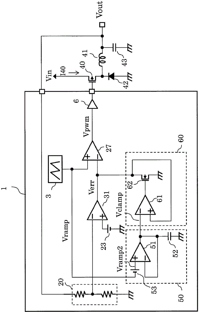
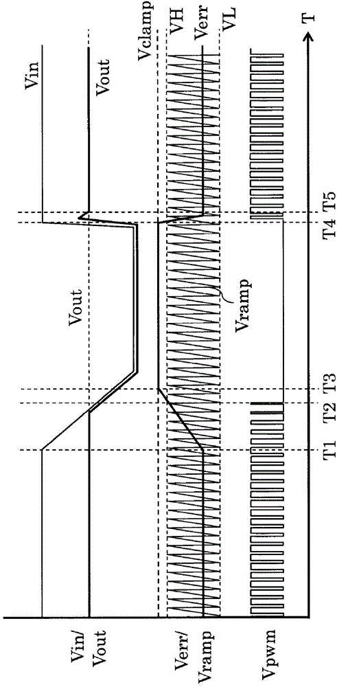
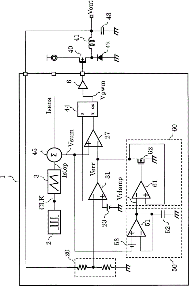
[0031] figure 1 It is a block diagram of the switching regulator of this embodiment. figure 1 The block diagram shown is an example of a voltage mode switching regulator.

[0032] The switching regulator of this embodiment has a switching regulator control circuit 1 , a power transistor 40 , a coil 41 , a diode 42 and a capacitor 43 .

[0033] The switching regulator control circuit 1 has a triangular wave generation circuit 3 , a reference voltage circuit 23 , an error amplifier 31 , a PWM comparator 27 , a buffer 6 , a voltage dividing circuit 20 , a peak hold circuit 50 and a clamp circuit 60 .

[0034] The peak hold circuit 50 has an operational amplifier 51 , a capacitor 52 and an offset circuit 53 . The clamp circuit 60 has an operational amplifier 61 and an Nch (N channel) transistor 62 .

[0035] The voltage dividing circuit 20 is connected between an input terminal to which an output voltage Vout is input and a ground terminal. The non-inverting input terminal o...


PUM


Abstract

Provided is a switching regulator configured to achieve a 100% Duty state and reduce an occurrence of an overshoot. The switching regulator has a configuration in which a clamp circuit configured to dynamically generate a clamp level clamps an output voltage of an error amplifier in accordance with a peak value of a triangular wave signal.

Description

technical field [0001] The present invention relates to a switching regulator that outputs a constant voltage, and more specifically, to a circuit for suppressing an overshoot of an output voltage. Background technique [0002] Switching regulators are used as voltage supply sources for circuits of various electronic devices. The function of the switching regulator is to output a constant voltage to the output terminal regardless of the voltage fluctuation of the input terminal. However, it is desired to output as close as possible to the output terminal in the region where the voltage of the input terminal drops and cannot maintain the set voltage of the output terminal. Set the voltage of the voltage. And even when the voltage of the input terminal recovers from this state and can supply the set voltage value to the output terminal, it is important to make the voltage of the output terminal transition to the set voltage without overshooting. Therefore, conventionally, th...

Claims


Application Information

Patent Timeline
Patent Type & Authority Applications(China)
IPC IPC(8): H02M1/32H02M3/155H02M1/00
CPCH02M2001/0025H02M3/156H02M1/0025H02M3/1566H02M3/157
Inventor 出口充康高田幸辅牧野哲也
Owner SII SEMICONDUCTOR CORP
Features
  • Generate Ideas
  • Intellectual Property
  • Life Sciences
  • Materials
  • Tech Scout
  • Unparalleled Data Quality
  • Higher Quality Content
  • 60% Fewer Hallucinations
Learn More