Tooth produced in a mold, and dental prosthesis

A tooth and mold technology, applied in the field of dental groups, can solve complex manual operations and other problems, and achieve the effect of improving retention characteristics and good retention

Inactive Publication Date: 2015-08-12
IVOCLAR VIVADENT AG
View PDF2 Cites 1 Cited by
  • Summary
  • Abstract
  • Description
  • Claims
  • Application Information

AI Technical Summary

Problems solved by technology

The individual teeth have to be configured correctly during demolding, which requires a lot of complex manual work

Method used


Image

  • Tooth produced in a mold, and dental prosthesis
  • Tooth produced in a mold, and dental prosthesis
  • Tooth produced in a mold, and dental prosthesis

Examples


Embodiment Construction

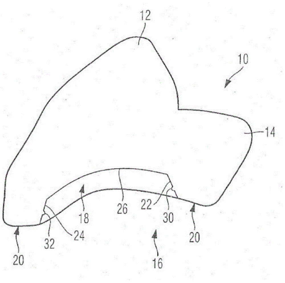
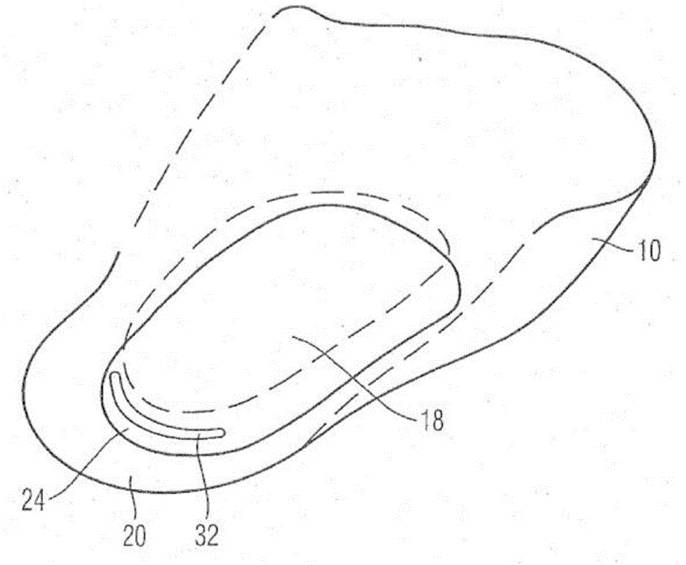
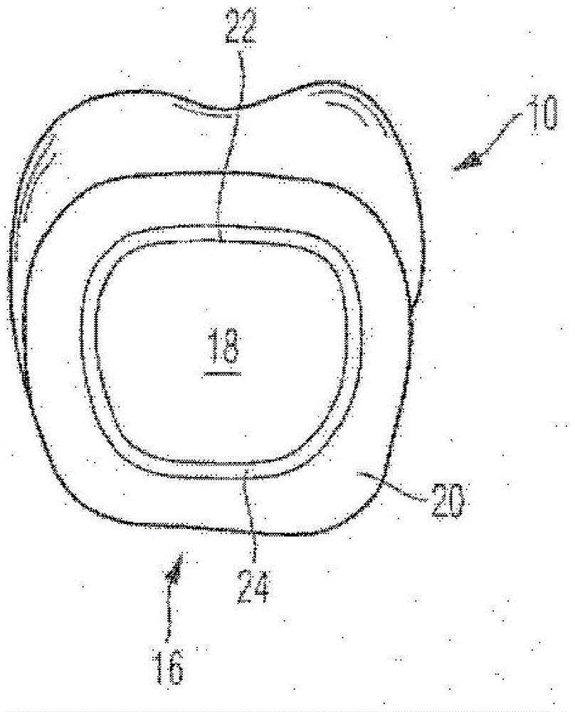
[0029] figure 1 The tooth 10 shown in has two protuberances 12 and 14 in a manner known per se. The base surface 16 extends on the underside of the tooth, thus on the side opposite the elevations 12 and 14 . The base area itself—that is to say even without taking into account the invention—is concave in the center and is therefore concave. A specially designed base cavity 18 according to the invention is cut into the base surface 16 as a bowl-shaped recess.

[0030] A base edge surface 20 substantially surrounding the base cavity 18 and having essentially the same width extends laterally of the base cavity. The cavity side wall 22 or 24 adjoins the base edge surface 20 . The sidewall of the cavity is in accordance with figure 1 In the illustration on the left side, that is, the cavity side wall 24 extends at an angle of about 75° relative to the base edge side 20, while on the right side, that is, the cavity side wall 22 extends at an angle relative to the The base edge...


PUM


Abstract

The teeth (12) is made from ceramic, composite or plastic and has a basal surface (16) that has a cavity (18), where the elliptic or circular cavity is adjusted at the basal surface. The cavity has a cavity edge (22,24) which is partially extended in an angle of more than 45 degrees, particularly more than 60 or 70 degrees, to the adjacent basal surface. The cavity is formed in cup-shaped manner with a flat cavity base (26) which is curved in flat, but S-shaped manner and is extended opposite to the surrounding basal surface in a parallel manner.

Description

technical field [0001] The invention relates to a tooth according to the preamble of claim 1 and a tooth set according to the preamble of claim 17 . Background technique [0002] It has long been known to use artificial teeth as dentures, which can be produced from various materials, for example ceramics, but also plastics or composite materials. Such teeth are available in the patient's mouth as part of a crown or via so-called abutments and implants. To manufacture such teeth, molds are usually provided that give the teeth different shapes close to natural teeth, in order to intentionally mimic the natural effect. Teeth of this type are also sometimes ground and are often also multi-layered in order to give them a translucent appearance. Finally, these teeth are also often post-treated with paint. [0003] The teeth that together form the dentition had developed at the turn of the 18th / 19th centuries. These teeth are usually fixed, mostly glued or additionally pinned, ...

Claims


Application Information

Patent Timeline
Patent Type & Authority Applications(China)
IPC IPC(8): A61C13/093A61C5/08A61C5/70
CPCA61C5/08A61C13/1006A61C5/70A61C13/081
Inventor K·哈根布奇M·埃德M·贝尔塔尼奥利C·弗赖K·兰巴赫
Owner IVOCLAR VIVADENT AG
Why Eureka
Try Eureka