
Dynamo-electrical machine with segmented stator structure and/or rotor structure

An electric power and machine technology, applied in the field of large electric power machines, can solve the problems of tedious work and cost, achieve the effect of simple bolt connection and reduce production costs

Active Publication Date: 2015-08-12
FLENDER GMBH
View PDF4 Cites 9 Cited by
  • Summary
  • Abstract
  • Description
  • Claims
  • Application Information

AI Technical Summary

Problems solved by technology

However, this eventually leads to too costly and tedious work especially in the final assembly of the assembly point

Method used


Image

  • Dynamo-electrical machine with segmented stator structure and/or rotor structure
  • Dynamo-electrical machine with segmented stator structure and/or rotor structure
  • Dynamo-electrical machine with segmented stator structure and/or rotor structure

Examples


Embodiment Construction

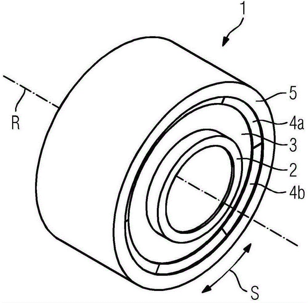
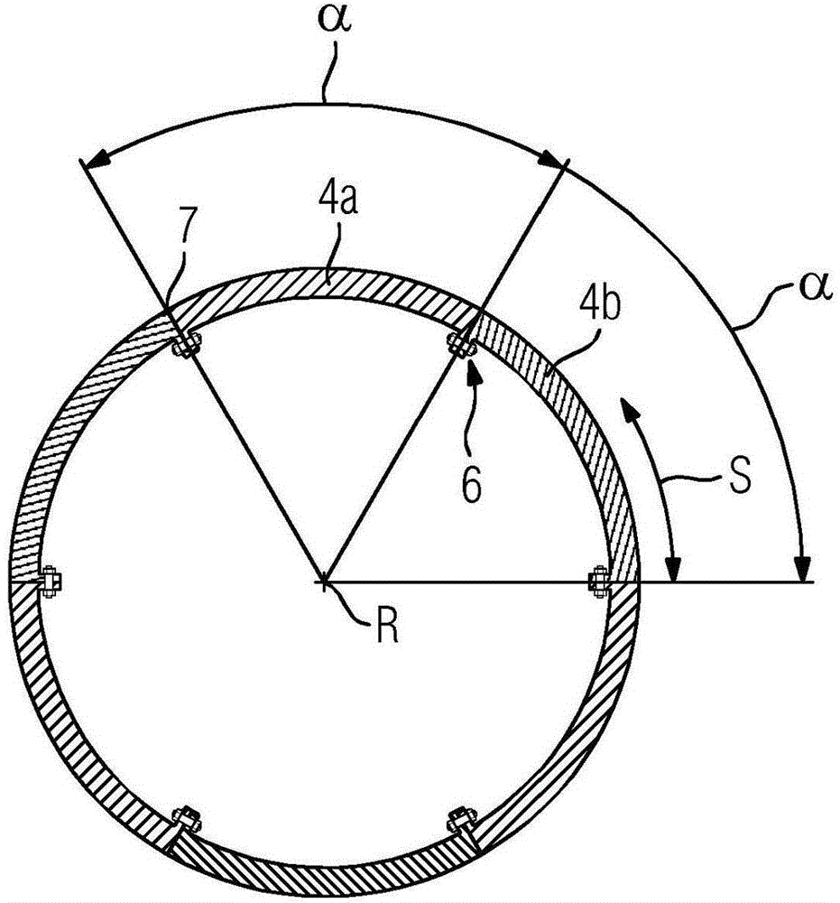
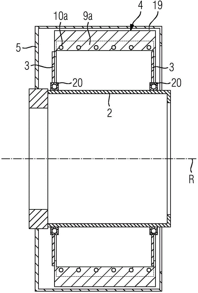
[0016] figure 1 The electrodynamic machine 1 according to the invention is shown in a perspective schematic illustration. The electrodynamic machine 1 has a rotor 5 arranged rotatably about an axis of rotation R, which rotates about the axis of rotation R in a direction of rotation S during operation of the electrodynamic machine. Furthermore, the electrodynamic machine 1 has a stationary stator 4 which, within the scope of the present exemplary embodiment, is positioned via a bearing on the shaft 2 by means of a carrier. The stator 4 has segments 4 a , 4 b arranged one behind the other in the direction of rotation S of the rotor 5 , of which only two segments have been designated for the sake of clarity. The segments are arranged in a ring here. The carrier device 3 connects the shaft 2 to these sections of the stator 4 via bearings. Within the framework of the present exemplary embodiment, the electrodynamic machine 1 is designed as a so-called outer rotor, ie the rotor 5...


PUM


Abstract

The invention relates to a dynamo-electrical machine (1) with a stator (4) and a rotor (5), which is rotatably arranged relative to the stator (4) about an axis of rotation (R). The stator (4) and / or the rotor (5) has a plurality of segments (4a, 4b) arranged one after another in the rotational direction (S) of the rotor (5). The segments (4a, 4b) have a flange (9a, 9b) at the side ends (13a, 13b) thereof in the rotational direction for connection to segments (4a, 4b) arranged adjoining one another in the rotational direction (S), and the flanges (9a, 9b) have at least one hole (10a, 10b) in the rotational direction (S). Flanges (9a, 9b) facing one another at the side ends (13a, 13b) in the rotational direction of segments (4a, 4b) arranged adjoining one another are connected to one another with a screw connection (6) passing through a hole (10a, 10b). To connect the flanges (9a, 9b) facing one another, a sleeve (8) having an external thread (8a) is arranged in the hole (10a, 10b) of at least one of the flanges (9a, 9b) facing one another at the side ends (13a, 13b) in the rotational direction. The hole (10b) of at least one of the flanges (9a, 9b) facing one another at the side ends (13a, 13b) in the rotational direction has an internal thread (11b), the internal thread (11b) of the hole (10b) being screwed into the sleeve (8). The sleeve (8) creates a spacing between the flanges (9a, 9b) facing one another. A screw (12) passes through the holes (10a, 10b) of the flanges (9a, 9b) facing one another at the side ends (13a, 13b) in the rotational direction, and through the sleeve (8).

Description

technical field [0001] The invention relates to an electrodynamic machine, especially a large electrodynamic machine with a power exceeding 1 MW. The machines are often designed in segmented configurations to ease transportation on streets and rails. In this case, either the rotor of the machine, the stator of the machine or both the stator and the rotor are designed in sections. When assembling these segments to form a complete stator ring or rotor ring, problems arise during the assembly of these segments due to the dependence on manufacturing tolerances of the respective segments. Difficulties in assembly arise, for example, due to tolerances in the graduation angles of the segments or due to misalignment of the through-openings of two segments which are arranged next to each other in the direction of rotation of the rotor or stator and which are to be connected to one another. Background technique [0002] Therefore, the gaps between the segments that arise during the ...

Claims


Application Information

Patent Timeline
Patent Type & Authority Applications(China)
IPC IPC(8): H02K1/28F16B5/02H02K1/12F16B43/02H02K7/18
CPCH02K2213/12H02K1/12Y02E10/725F16B43/02F16B5/0233F16B19/02H02K7/1838F03D9/25Y02E10/72H02K1/18H02K1/28F03D15/20F03D80/70
Inventor 乌尔里希·哈特曼马丁·容格丹尼尔·克尔马斯弗里德里克·里希特克劳斯·席费雷尔戈登·特罗吉施
Owner FLENDER GMBH
Learn More