

Fuming device of smoke wind tunnel
A technology of smoke generating device and smoke wind tunnel, which is applied in the direction of measuring device, instrument, aerodynamic test, etc., can solve the problems of smoke generating device that cannot achieve continuous smoke flow, increase the complexity of the experimental process, etc., and achieve the same size , Balanced spacing, easy to flow up and down
- Summary
- Abstract
- Description
- Claims
- Application Information
AI Technical Summary
Problems solved by technology
Method used
Image

Examples
Embodiment Construction
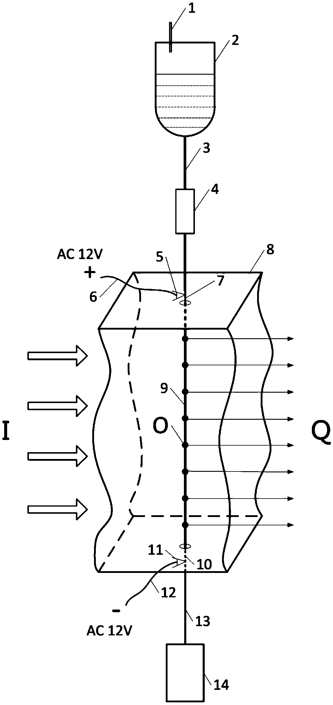
[0019] see figure 1 , the embodiment of the present invention is provided with a fuel tank breather pipe 1, a fuel tank 2, an oil delivery hose 3, a smoke oil flow controller 4, a positive electric clip 5, a negative electric clip 11, a positive lead wire 6 for a power supply, a negative lead wire 12 for a power supply, and a positive lead wire Column 7, negative pole terminal 10, wind tunnel experiment section hole body 8, metal wire 9, insulated connection wire 13, smoke oil collector 14 and DC high voltage power supply.
[0020] The oil tank 2 is connected to the metal wire 9 through the oil delivery hose 3, the top of the oil tank 2 is provided with a fuel tank vent pipe 1 to communicate with the atmosphere, and the oil delivery hose 3 between the oil tank 2 and the metal wire 9 is installed with a smoke oil flow controller 4 The oil hose 3 and the metal wire 9 are respectively connected to the two ends of the positive terminal 7, and the positive terminal 7 is fixed at th...
PUM
 Abstract
Description
Claims
Application Information