Scattering correction method for projected image and device

A projection image and scattering image technology, applied in the field of projection images, can solve the problems of inaccurate estimation of scattering, particularly obvious distribution deviation, and failure to consider the contribution of secondary and higher-order scattering, so as to improve image quality and reduce unpleasant effect

Active Publication Date: 2015-08-19
SHANGHAI UNITED IMAGING HEALTHCARE
View PDF8 Cites 23 Cited by
  • Summary
  • Abstract
  • Description
  • Claims
  • Application Information

AI Technical Summary

Problems solved by technology

In the U.S. Patent Publication No. US6104777, an analytical method was introduced to estimate Compton scattering and Rayleigh scattering, but this technology did not consider the contribution of secondary and higher order scattering, and did not fully consider the photon energy response of the detector Effect on Scattering
In the public document Phys.Med.Biol.55 1295, 2010, J.L.Ducote et al., there is an equivalent PMMA modality to calculate the scattering kernel, and the method of descattering by deconvolution operation on the projected image, but this kind of technology The disadvantage is that the scatter estimation is inaccurate if the density equivalent material is used instead of human tissue, especially for dense breasts, the deviation between the estimation and the real scatter distribution is particularly obvious

Method used


Image

  • Scattering correction method for projected image and device
  • Scattering correction method for projected image and device
  • Scattering correction method for projected image and device

Examples


Embodiment Construction

[0033] In order to make the above objects, features and advantages of the present invention more comprehensible, specific implementations of the present invention will be described in detail below in conjunction with the accompanying drawings. In the following description, specific details are set forth in order to provide a thorough understanding of the present invention. However, the present invention can be implemented in many other ways than those described here, and those skilled in the art can make similar extensions without departing from the connotation of the present invention. Accordingly, the present invention is not limited to the specific embodiments disclosed below.

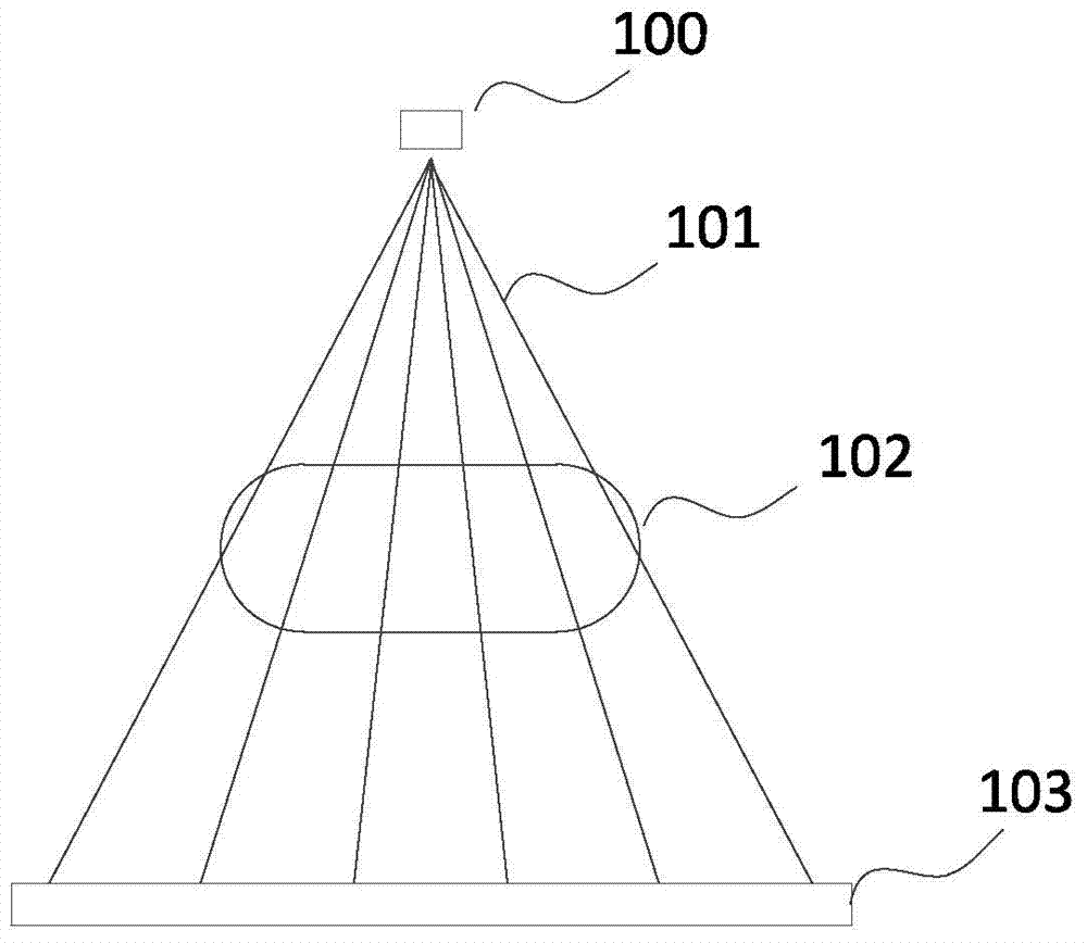
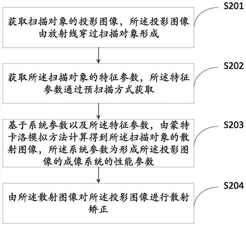
[0034] The present invention provides a scattering correction method for projected images, such as figure 2 shown, including the following steps:

[0035] Step S201 , acquiring a projection image of the scanned object, where the projected image is formed by radiation passing through the scanned o...


PUM


Abstract

The invention provides a scattering correction method for a projected image and a device, wherein the scattering correction method comprises: obtaining the projected image of a scanned object; obtaining the characteristic parameter of the scanned object; obtaining the scattering image of the scanned object through calculation according to the Monte Carlo simulation method on the basis of a system parameter and the characteristic parameter; carrying out scattering correction to the projected image through the scattering image. According to the technical scheme of the invention, on the premise of not increasing radiation dosage absorbed by a patient, the discomfort and pain suffered by the patient in the checking process are reduced, in consideration of the impact of physical factors such as secondary and higher scattering, energy response and the like on scattering, the calculation for the scattering is closer to the physical situation, and the image quality of the projected image is enhanced.

Description

technical field [0001] The invention relates to the field of projected images, in particular to a method and device for correcting scattering of projected images. Background technique [0002] The projection image (projection image) formed by the radiation beam passing through the scanning object is an important reference for patient diagnosis in clinical practice. guide the treatment plan. Common radiation includes electromagnetic radiation (electro-magnetic radiation) rays, such as radio waves, visible light, X-rays, particle rays, and neutron rays. It is not only applied to medical images, but also can be applied to industrial imaging, such as for industrial inspection, to view the internal structure of the object. [0003] The specific formation process of the projected image is, for example, figure 1 As shown, the radiation generating device 100 generates radiation 101 (such as X-rays) with substantially uniform energy. The radiation 101 passes through the scanning o...

Claims


Application Information

Patent Timeline
Patent Type & Authority Applications(China)
IPC IPC(8): A61B6/00A61B5/00G01C11/00G06T11/00
Inventor 陈鸣之朱建伟
Owner SHANGHAI UNITED IMAGING HEALTHCARE
Why Eureka
Try Eureka