Alloy plate electromagnetic punching and flanging forming method and device

An alloy plate and punching technology, which is applied in the field of electromagnetic punching and flanging forming of alloy plates and devices, can solve the problems of reducing forming efficiency, increasing manufacturing cost, difficult positioning, etc., so as to improve forming limit, improve production efficiency, and overcome positioning effect of the problem

Inactive Publication Date: 2015-08-19
FUZHOU UNIVERSITY
View PDF8 Cites 17 Cited by
  • Summary
  • Abstract
  • Description
  • Claims
  • Application Information

AI Technical Summary

Problems solved by technology

The room temperature formability of aluminum alloy is poor, and it is difficult to form complex parts by traditional stamping technology, and it is easy to crack at the edge of deep-drawn fillets and flanging holes, and the forming quality is unstable and the forming limit is low. These are great constraints. With the development of traditional stamping technology
[0003] Therefore, many scholars at home and abroad have begun to actively explore new stamping processes in the traditional stamping process. Because of the technical advantages of electromagnetic forming, such as fast loading speed and high forming precision, researchers have begun to use electromagnetic forming technology for plastic forming, as proposed in the patent CN102248693A An electromagnetic drive forming method and device. The method uses pulsed electromagnetic force to drive the punch to accelerate, and the punch hits the workpiece to complete the film forming of the workpiece and the die. However, the rigid punch increases the manufacturing cost and easily scratches the workpiece. For the for

Method used


Image

  • Alloy plate electromagnetic punching and flanging forming method and device
  • Alloy plate electromagnetic punching and flanging forming method and device
  • Alloy plate electromagnetic punching and flanging forming method and device

Examples


Embodiment Construction

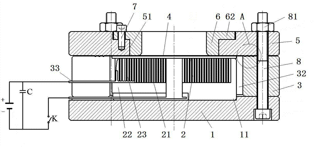
[0031] like Figure 1~7 As shown, in the present invention, an alloy plate electromagnetic punching flanging forming method comprises the following steps:

[0032] (1) Install flat-plate helical coil group 2: First, a flat-plate helical coil group 2 for providing electromagnetic repulsion is fixedly installed in the positioning groove 11 of the base 1, and the positive and negative poles of the flat-plate helical coil group 2 are passed through the capacitor group C is connected in series with the discharge control switch K, the capacitor group C is connected in parallel with the power supply, and a lower mold 3 is provided outside the flat spiral coil group 2;

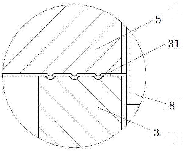
[0033] (2) Install the blank 4: then place the blank 4 at the predetermined position on the annular lower mold 3, the selected blank 4 is preferably an aluminum alloy sheet, then place the upper mold 5, and use the stretching provided on the upper end surface of the lower mold 3 The rib 31 clamps and positions the bl...


PUM


Abstract

The invention relates to an alloy plate electromagnetic punching and flanging forming method. The alloy plate electromagnetic punching and flanging forming method includes the first step of installing a flat plate spiral coil assembly, the second step of installing a blank, the third step of conducting discharging punching forming, the fourth step of conducting discharging flanging forming, and the fifth step of taking out a formed part. The invention further relates to an alloy plate electromagnetic punching and flanging forming device. An adopted electromagnetic forming tool is simple, no male die needs to be manufactured, and the problems caused by a fit clearance between a female die and the male die are solved. The forming process is completed instantly, ductility and forming limit of materials can be improved, and the problem that cracks are generated in the flanging process can be well solved. Besides, positioning problems caused by die change during multi-procedure forming in existing electromagnetic forming technologies are solved, the problem that cost is increased due to die disassembling and assembling is solved, and production efficiency is greatly improved.

Description

technical field [0001] The invention relates to an alloy plate electromagnetic punching flanging forming method and device. Background technique [0002] Stamping is the most common manufacturing and processing technology, usually using a die to apply pressure to the material on a press to separate or deform it. Due to the small gap between the punch and the die in the stamping process, it is difficult to adjust the die, and the friction between the punch and the side of the die and the material increases, and it is difficult to change the die and position during multiple processes, which reduces the service life of the die and increases the cost. At the same time, the lightweight of automobiles and aircraft has gradually become the development trend of the future industry. The application of lightweight and difficult-to-form materials such as aluminum alloys, high-strength steels and composite materials in advanced manufacturing fields such as automobiles and aerospace is i...

Claims


Application Information

Patent Timeline
IPC IPC(8): B21D35/00B21D28/26B21D19/08
Inventor 邓将华黄伍平程溧詹艳然江星莹
Owner FUZHOU UNIVERSITY
Why Eureka
Try Eureka