Conveying mechanism of metal wire cut-off machine

A technology of cutting machine and metal wire, applied in the field of transport mechanism of copper wire cutting machine, can solve the problem of inability to transport large and small load-bearing containers, etc., and achieve the effect of improving firmness and broadening the scope of application

Inactive Publication Date: 2015-08-19
KUNSHAN DEYOU MACHINERY EQUIP
View PDF8 Cites 10 Cited by
  • Summary
  • Abstract
  • Description
  • Claims
  • Application Information

AI Technical Summary

Problems solved by technology

[0003] The technical problem solved by the present invention: the wire cutting machine in the prior art, the positions of the two support plates of the tra

Method used


Image

  • Conveying mechanism of metal wire cut-off machine
  • Conveying mechanism of metal wire cut-off machine
  • Conveying mechanism of metal wire cut-off machine

Examples


Embodiment Construction

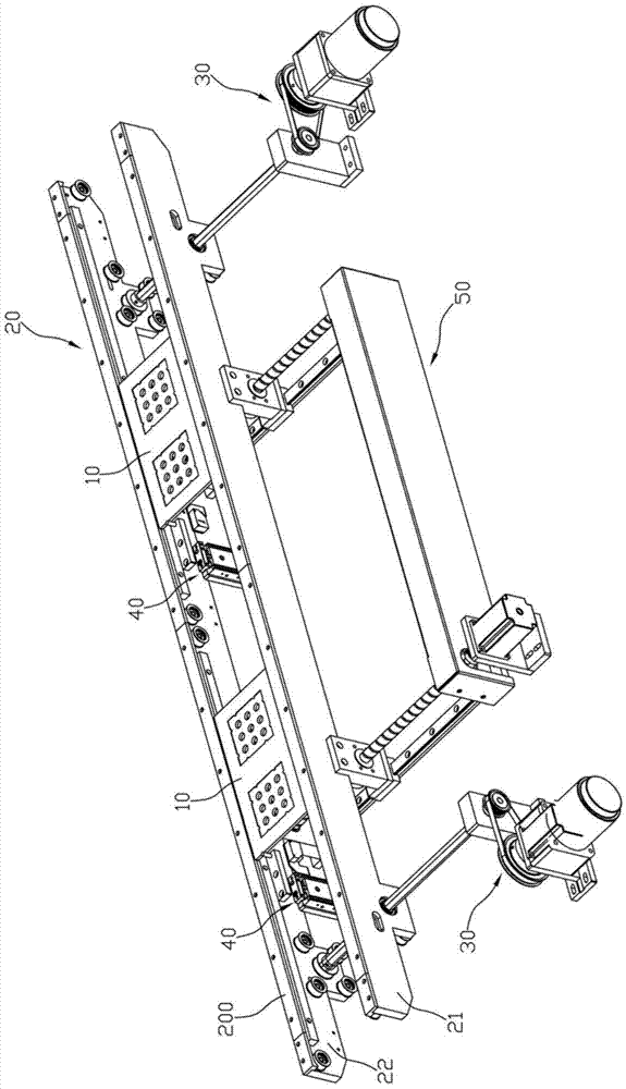
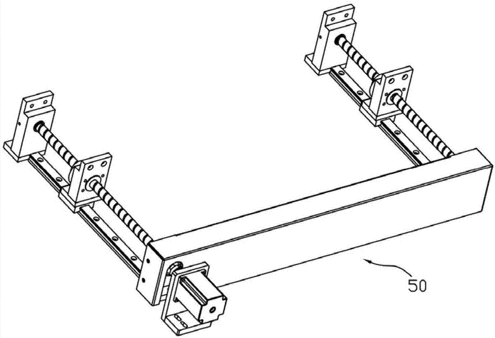
[0025] Such as figure 1 As shown, a transport mechanism of a wire cutting machine includes a load plate 10 , a transport track 20 , a drive system 30 , a positioning device 40 , and a screw mechanism 50 .

[0026] Such as Figure 7 As shown, a groove 100 is defined on the carrier board 10 , a plurality of through holes 101 are defined in the groove 100 , and a plurality of protrusions 102 are formed on the inner wall of the groove 100 .

[0027] Such as figure 1 As shown, the transport track 20 includes a first support plate 21 and a second support plate 22, a guide bar 200 installed on the top of the first support plate 21 and the second support plate 22, a guide strip 200 installed on the top of the first support plate 21 and the second support plate The conveyor belt inside the support plate 22 and below the guide strips 200 , the carrier plate 10 is placed on the conveyor belt and between the two guide strips 200 .

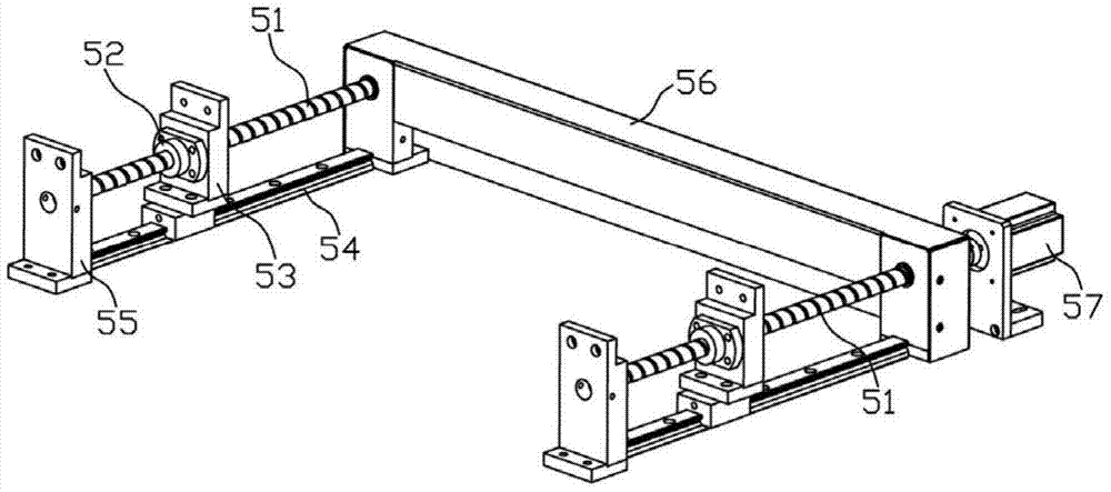
[0028] Such as Figure 5 As shown, the drive system ...


PUM


Abstract

The invention discloses a conveying mechanism of a metal wire cut-off machine. The conveying mechanism comprises bearing plates, a conveying rail, a drive system, a positioning device and a lead screw mechanism. The conveying rail comprises two supporting plates. The lead screw mechanism comprises a lead screw, an internal threaded piece, a slide block and a guide rail. The lead screw is meshed with the internal threaded piece which is fixed to the slide block. The first supporting plate is fixed to the slide block. The length direction of the first supporting plate is perpendicular to the length direction of the lead screw. Through the lead screw mechanism, the distance between the first supporting plate and the second supporting plate can be adjusted. Through the technical scheme, bearing plates of various sizes can be conveyed through the conveying rail of the metal wire cut-off machine, and the application range of the conveying rail is enlarged.

Description

Technical field: [0001] The technical field of wire cutting of the present invention, in particular, relates to a transport mechanism of a wire cutting machine, in particular to a transport mechanism of a copper wire cutting machine. Background technique: [0002] It is generally known that if a processor cuts the wire wound on the reel into equal-length wire segments, a wire cutter needs to be used. After the cutter in the wire cutter cuts the wire, the resulting wire segments need to be transported out of the wire cutter. Due to the relatively small volume of the wire segments, during transportation, a carrying container is required to load the wire segments. Therefore, transporting the wire pieces out of the wire cutter requires a transport track, a carrying container running on the transport track. The transportation track in the prior art mainly includes two support plates, a guide bar installed on the top surface of the support plates, and a conveyor belt installed o...

Claims


Application Information

Patent Timeline
IPC IPC(8): B21F11/00
CPCB21F11/00B65G17/12
Inventor 许诚发
Owner KUNSHAN DEYOU MACHINERY EQUIP
Why Eureka
Try Eureka