Efficient pneumatic jewel channel-setting device

A high-efficiency, stone-positioning technology, applied in the field of high-efficiency pneumatic inlaying and inlaying devices, can solve the problems of low precision, inability to adapt to gems and zircons, and low efficiency, and achieve the effect of improving efficiency and precision and good effect of inlaying

Active Publication Date: 2015-08-19
东莞市杰安腾精密五金制品有限公司
View PDF6 Cites 1 Cited by
  • Summary
  • Abstract
  • Description
  • Claims
  • Application Information

AI Technical Summary

Problems solved by technology

[0002] The existing inlay technology is generally traditional manual inlay, or inlay one by one in a single machine. The former is labor-intensive and time-consuming, and the efficiency is low. Standardized pr...

Method used


Image

  • Efficient pneumatic jewel channel-setting device
  • Efficient pneumatic jewel channel-setting device
  • Efficient pneumatic jewel channel-setting device

Examples


Embodiment 1

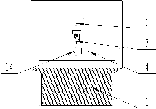
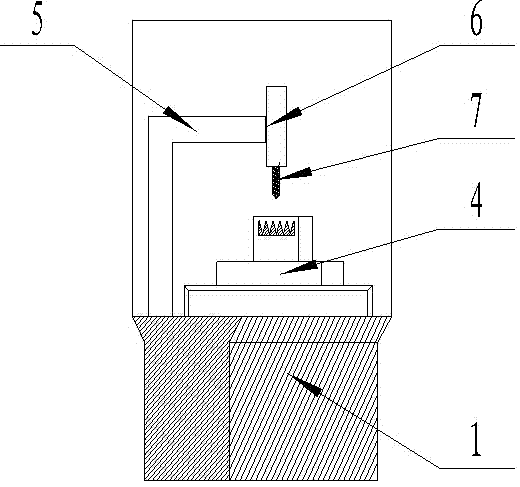
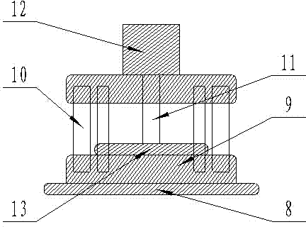
[0024] like Figure 1-3 As shown, a high-efficiency pneumatic setting stone device includes a CNC numerical control machine for processing stone holes and stone grooves and a pressing device for pressing gemstones on the surface of a workpiece; the CNC numerical control machine includes a machine base 1. X driving shaft 2 and Y driving shaft installed on the upper surface of the machine base 3. A workbench located on the upper surface of the machine base and driven by the X driving shaft and Y driving shaft for horizontal displacement 4. Fixedly installed on the machine base The pillar 5, the Z drive shaft 6 installed on the pillar and the drill bit 7 which is installed on the Z drive shaft and moves up and down under its drive; Die 9, the guide column 10 that is installed on the base, the column 11 that is installed on the base, the cylinder 12 that is installed on the column and the upper mold 13 that is driven by cylinder and moves up and down along the guide column is form...

Embodiment 2

[0031] like Figure 4 As shown, the difference between this embodiment and Embodiment 1 is that the X driving axis on the machine base is canceled on the CNC machine, the Y driving axis on the machine base and the A axis on the workbench are reserved, and the whole device is aimed at circular Or the cylindrical workpiece is processed with the stone hole and the stone groove, and the stone hole and the stone groove on the surface of the cylindrical or circular workpiece are processed through the rotation of the A axis and the up and down movement of the Y drive shaft. Other parts are identical with embodiment 1.

Embodiment 3

[0033] like Figure 5 As shown, the difference between this embodiment and Embodiment 1 is that the A-axis on the workbench is canceled on the CNC machine, and the X drive axis and Y drive axis on the machine base are reserved, and the whole device is used for stone-position holes for flat workpieces. For the processing of stone slots, the processing of stone slots and stone slots on the surface of the flat workpiece is realized by moving the X drive shaft and the Y drive shaft up and down, left and right. Other parts are identical with embodiment 1.


PUM


Abstract

The invention discloses an efficient pneumatic jewel channel-setting device. The efficient pneumatic jewel channel-setting device comprises a CNC numerical control machine for processing a jewel position hole and a jewel position channel and a channel-setting device body for channel setting of a jewel on the workpiece surface. The CNC numerical control machine comprises a machine base 1, an X driving shaft 2 and a Y driving shaft 3, a worktable 4 located on the upper surface of the machine base and driven by the X driving shaft 2 and the Y driving shaft 3 to perform horizontal displacement, a supporting column 5 fixedly installed on the machine base, a Z driving shaft 6 installed on the supporting column and a drill mouth 7 installed on the Z driving shaft and driven by the Z driving shaft to perform vertical movement, wherein the X driving shaft 2 and the Y driving shaft 3 are installed on the upper surface of the machine base. The channel-setting device body comprises a base 8, a lower die 9 installed on the base, a guide column 10 installed on the base, a column 11 installed on the base, an air cylinder 12 installed on the column and an upper die 13 driven by the air cylinder and performing vertical motion along the guide column. The efficient pneumatic jewel channel-setting device has the advantages of achieving full-automatic processing and channel setting and being high in working efficiency.

Description

technical field [0001] The invention relates to the field of gemstone processing, in particular to a high-efficiency pneumatic pressing device for setting stones. Background technique [0002] The existing inlay technology is generally traditional manual inlay, or inlay one by one in a single machine. The former is labor-intensive and time-consuming, and the efficiency is low. Standardized production cannot be realized. The existing efficiency is low and the precision is not high, so it cannot adapt to large batches. Pre-setting of gemstones and zircons and special positions (curved surface, R surface). Contents of the invention [0003] The object of the present invention is to solve the above-mentioned problems, and has designed a kind of high-efficiency pneumatic forcing inlaid stone device. [0004] The technical solution of the present invention to achieve the above-mentioned purpose is a high-efficiency pneumatic setting stone device, including a CNC numerical contr...

Claims


Application Information

Patent Timeline
IPC IPC(8): B23P5/00
CPCB23P5/00
Inventor 肖洪安
Owner 东莞市杰安腾精密五金制品有限公司
Why Eureka
Try Eureka