
Multistage equal deformation elastic positioning and clamping device

An elastic positioning and clamping technology, which is applied in positioning devices, clamping devices, clamping, etc., can solve the problem that the processed parts cannot be accurately positioned and clamped, the precision of the parts is out of tolerance, and the mandrel cannot be completely fitted, etc. problem, to achieve the effect of simple structure, high positioning and clamping precision, and strong flexibility

Inactive Publication Date: 2015-08-19
襄阳长源东谷实业股份有限公司
View PDF4 Cites 0 Cited by
  • Summary
  • Abstract
  • Description
  • Claims
  • Application Information

AI Technical Summary

Problems solved by technology

[0003] 1. The inner taper hole of the collet with a taper of 10 degrees is matched with the mandrel. When the mandrel is pulled backward by the oil cylinder, the deformation of the collet increases, and the inner taper hole is greater than 10 degrees, while the taper of the mandrel It is still 10 degrees, the taper of the inner taper of the collet and the mandrel with the outer cone of 10 degrees cannot be completely contacted, only a part is in a linear combination state, and most of the conical surfaces have a large gap, so that the inner part of the collet The taper hole and the outer taper mandrel cannot fit perfectly
[0004] 2. Due to the large gap between the inner taper hole of the collet and the mandrel, the outer circle of the collet does not expand evenly in a straight line, so that the processed parts cannot be accurately positioned and clamped, and the clamping force is not enough. Parts are prone to vibration during processing, which will damage equipment and tools, so that the coaxiality, cylindricity, runout, perpendicularity to the end face, and position of the corresponding hole system cannot meet the requirements of the drawing. Process requirements lead to serious out-of-tolerance process accuracy and unstable quality of processed parts, causing great economic losses and waste of resources to enterprises

Method used


Image

  • Multistage equal deformation elastic positioning and clamping device

Examples


Embodiment Construction

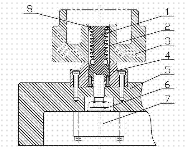
[0016] Such as figure 1 As shown, the multi-stage toothed elastic jacket 2 is fixed on the positioning base 4, the multi-stage toothed tie rod mandrel 1 is arranged in the inner hole of the multi-stage toothed elastic jacket 2, and the multi-stage toothed tie rod core The tooth structure of the shaft 1 and the multi-stage toothed elastic jacket 2 is composed of a horizontal plane symmetrically distributed along its center line and an inclined plane 10-30 degrees from the horizontal plane. The top of the multi-stage toothed elastic jacket 2 has Dustproof ring 8; positioning base 4 is installed on clamp body 5; piston rod 6 of magnetic induction type oil cylinder 7 is connected with external thread of multi-stage toothed tie rod mandrel 1 through its own internal thread, and magnetic induction type oil cylinder 7 is installed In the clamp body 5.

[0017] Working principle of the present invention:

[0018] 1. When loosened, the piston rod 6 of the magnetic induction oil cylin...


PUM


Abstract

A multistage equal deformation elastic positioning and clamping device is used for automatically positioning and clamping workpieces. A multistage tooth-shaped elastic clamping jacket is fixed on a positioning base, and a multistage tooth-shaped pull rod mandrel is arranged in an inner hole of the multistage tooth-shaped elastic clamping jacket. The positioning base is arranged on a clamp body. A piston rod of a magnetic induction type oil cylinder is connected with the multistage tooth-shaped pull rod mandrel through an internal thread of the piston and an external thread of the multistage tooth-shaped pull rod mandrel. The magnetic induction type oil cylinder is mounted in the clamp body, and a dustproof ring is arranged on the top of the multistage tooth-shaped elastic clamping jacket. The tooth-shaped structure of the multistage tooth-shaped pull rod mandrel and the multistage tooth-shaped elastic clamping jacket is composed a horizontal plane which is symmetrically distributed along the center line of the tooth-shaped structure and an oblique plane which forms an angle of 10-30 degree with the horizontal plane. The multistage equal deformation elastic positioning and clamping device has the advantages of being high in positioning and clamping precision, easy to operate, stable and reliable in performance, high in anti-interference performance and universality and the like.

Description

technical field [0001] The invention relates to the technical field of mechanical equipment, in particular to an automatic positioning clamp for processing inner and outer circular parts, gears, shells, boxes and the like. Background technique [0002] At present, how to prevent the coaxiality, verticality and processing deformation of the parts for the shell and gear parts that use inner hole positioning to process the inner and outer circles is a difficult problem in the machining industry. The current solution is to use the inner hole positioning spring expansion collet to achieve the purpose of positioning and clamping parts, but this positioning collet has the following disadvantages: [0003] 1. The inner taper hole of the collet with a taper of 10 degrees is matched with the mandrel. When the mandrel is pulled backward by the oil cylinder, the deformation of the collet increases, and the inner taper hole is greater than 10 degrees, while the taper of the mandrel It i...

Claims


Application Information

Patent Timeline
Patent Type & Authority Applications(China)
IPC IPC(8): B23Q3/08
CPCB23Q3/08B23Q2703/04
Inventor 杨宜勇宋光芳孙尚超杨成陈昌均
Owner 襄阳长源东谷实业股份有限公司
Learn More