Locally induced attached rotary ultrasonic head based on machine tool

A technology of ultrasonic head and machine tool, which is applied in the direction of metal processing machinery parts, clamping, support, etc. It can solve the problems of low energy transfer efficiency, troublesome tool change, and oversized size, so as to reduce the possibility of interference and meet the requirements of high-power processing. , The effect of reducing the number of parts

Inactive Publication Date: 2015-08-19
TIANJIN UNIV
View PDF5 Cites 4 Cited by
  • Summary
  • Abstract
  • Description
  • Claims
  • Application Information

AI Technical Summary

Problems solved by technology

However, the current ultrasonic processing devices have many defects, such as the complex structure of the ultrasonic processing head, which leads to large energy loss and low efficiency during the transmission process; there are two types of non-contact energy transmission: (1) end face Transmission, its defect is that the accuracy of the magnetic core layout is high, if the two ends cannot be kept parallel, the efficiency of energy transmission will be greatly reduced
(2) Cylindrical transmission, the transmission efficiency is stable, but because two magnetic rings are arranged concentrically, and the main side magnetic core needs to be fixed, the size is too large. Although the ultrasonic processing head can be attached to the machine tool, the tool change It is troublesome and difficult to realize the automatic tool change of the machine tool
Therefore, it affects the use and promotion of rotary ultrasonic machining in automated machining centers

Method used


Image

  • Locally induced attached rotary ultrasonic head based on machine tool
  • Locally induced attached rotary ultrasonic head based on machine tool
  • Locally induced attached rotary ultrasonic head based on machine tool

Examples


Embodiment Construction

[0024] The technical solutions of the present invention will be described in further detail below in conjunction with the accompanying drawings and specific embodiments, and the described specific embodiments are only to illustrate the present invention, and are not intended to limit the present invention.

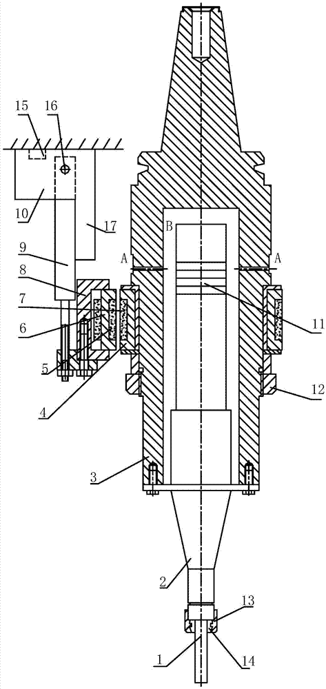
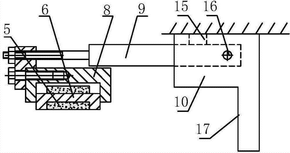
[0025] Such as figure 1 As shown, the present invention is based on a local induction rotary ultrasonic head of a machine tool attachment, including a tool handle 3 connected to an ultrasonic vibration working device and a non-contact collector ring, and one end of the tool handle 3 is connected to the The ultrasonic vibration working device is connected, where the precision of the tool handle 3 and the flange contact surface is required to be high, otherwise the coaxial arrangement of the tool 1, the horn 2 and the tool handle 3 cannot be realized, which affects the processing quality; the tool handle The other end of 3 is installed on the main shaft of the machine tool, ...


PUM


Abstract

The invention discloses a locally induced attached rotary ultrasonic head based on a machine tool. The locally induced attached rotary ultrasonic head based on the machine tool comprises a hilt, wherein the hilt is connected with an ultrasonic vibration working device; a non-contact type current collecting ring sleeves the hilt; the rotary axis of the ultrasonic vibration working device, the rotary axis of the hilt and the rotary axis of the current collecting ring are positioned on the same straight line; the non-contact type current collecting ring comprises a main side magnetic core and a secondary side magnetic core; the main side magnetic core consists of an arc-shaped or rectangular permeability magnetic material; the secondary side magnetic core consists of an annular permeability magnetic material; the main side magnetic core and the secondary side magnetic core are coaxial; coils are respectively wound on the main side magnetic core and the secondary side magnetic core; the main side magnetic core is connected with a body of the machine tool through a connecting device; and the secondary side magnetic core sleeves the hilt fixedly. The structure of the attached rotary ultrasonic head is simplified, abrasion and energy loss of parts in a rotary ultrasonic machining process are reduced, and the working reliability of the locally induced attached rotary ultrasonic head is improved. Owing to transmission of locally induced non-contact energy, knives are changed simply, and change of the knives can be controlled automatically.

Description

technical field [0001] The invention is a rotary ultrasonic processing device with local induction, which is characterized by simple structure, low energy loss, convenient tool replacement and automatic control. Background technique [0002] Ultrasonic machining is often used in the processing of hard and brittle materials, which can effectively improve the surface quality of workpieces, reduce surface roughness and improve machining accuracy. However, the current ultrasonic processing devices have many defects, such as the complex structure of the ultrasonic processing head, which leads to large energy loss and low efficiency during the transmission process; there are two types of non-contact energy transmission: (1) end face The disadvantage of transfer is that the accuracy of the magnetic core layout is high. If the two ends cannot be kept parallel, the efficiency of energy transfer will be greatly reduced. (2) Cylindrical transmission, the transmission efficiency is sta...

Claims


Application Information

Patent Timeline
Patent Type & Authority Applications(China)
IPC IPC(8): B23Q3/157B23Q27/00
CPCB23Q3/157B23Q27/00
Inventor 林彬栾雨佳朱学明张晓峰
Owner TIANJIN UNIV
Why Eureka
Try Eureka