Vehicle cooling circuit

A cooling circuit and coolant pipeline technology, applied in liquid cooling, vehicle components, vehicle energy storage, etc., can solve the problems of output refrigeration power, refrigerator can not, cooling liquid can not be reduced according to needs, etc., to achieve a simplified system architecture. Effect

Active Publication Date: 2015-08-19
LIEBHERR TRANSPORTATION SYST
View PDF7 Cites 25 Cited by
  • Summary
  • Abstract
  • Description
  • Claims
  • Application Information

AI Technical Summary

Problems solved by technology

This coolant circuit line has the disadvantage that the large amount of cooling liquid flowing through the evaporator of the refrigeration circuit cannot be reduced as needed
For this reason, the refrigerating machine cannot be used to export cooling power to the outside world in part-load operation, when the cooling power can largely be introduced into the coolant circuit by the evaporator

Method used


Image

  • Vehicle cooling circuit
  • Vehicle cooling circuit
  • Vehicle cooling circuit

Examples


Embodiment Construction

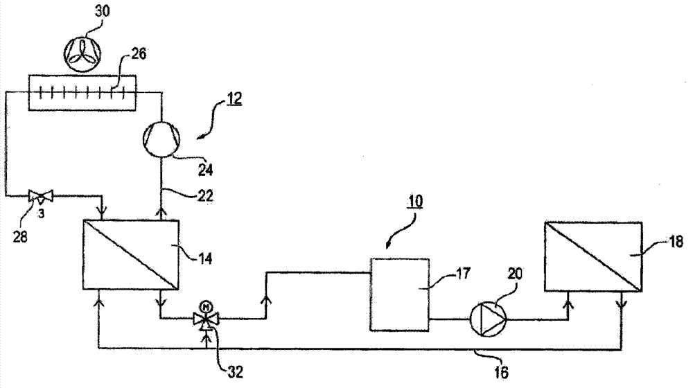
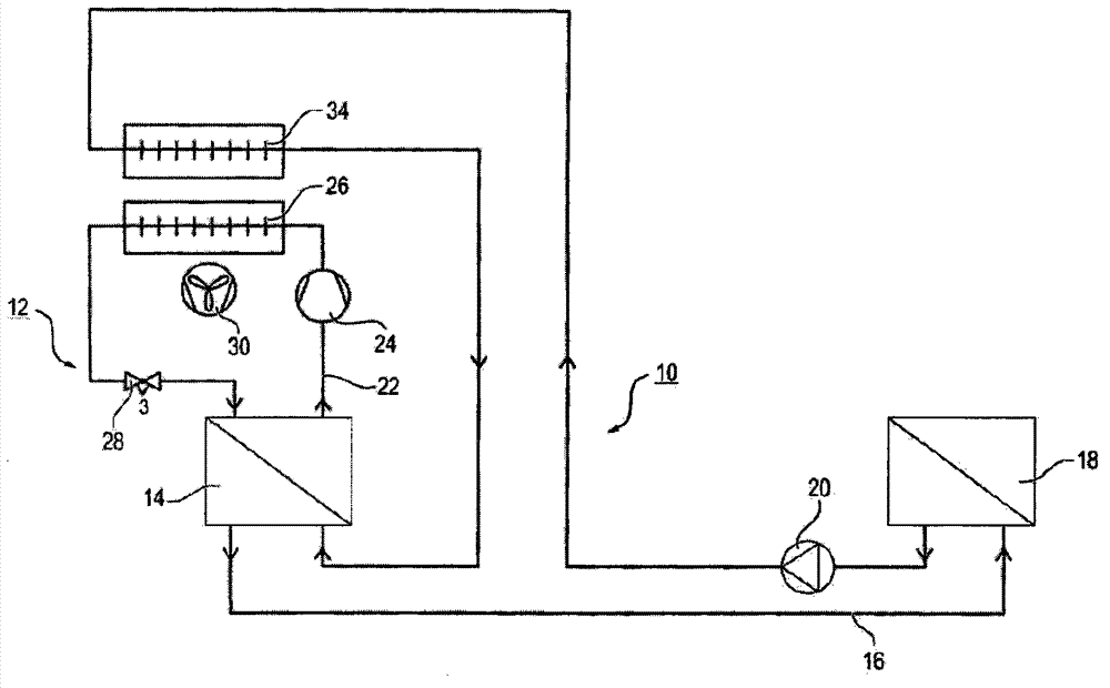
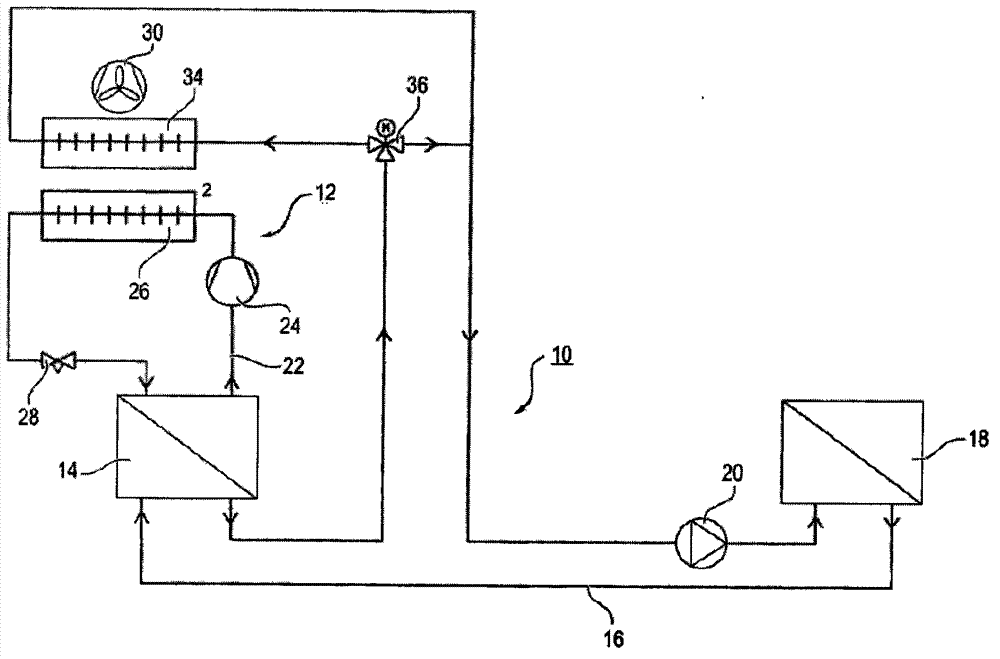
[0019] Such as image 3 As shown, the coolant circuit 10 of the first embodiment of the invention is connected to the cooling medium circuit 12 via a heat exchanger 14 configured as an evaporator. The coolant circuit has a coolant line 16 in which the coolant is passed by a pump 20 along the image 3 Convey in the direction of the arrow shown. The heated device 18 , for example the vehicle battery of an electric vehicle, is cooled by the coolant. Furthermore, the coolant circuit is provided with a refrigerant 34 which is cooled by a cooling air flow which is cooled by the airflow of the vehicle and / or by the fan 30 . Further cooling of the coolant circuit takes place via a heat exchanger 14 configured as an evaporator in a cooling medium circuit connected to the coolant circuit. In a known manner, the coolant circuit 12 comprises, in addition to the evaporator 12 , a coolant line 22 , a compressor 24 , a condenser 26 and a pressure relief valve 28 . The aforementioned word "...


PUM


Abstract

The present disclosure relates to a vehicle cooling circuit for cooling a temperature-increasing device, in particular a battery, by means of a coolant conducted in a coolant circuit, wherein the coolant circuit has a heat exchanger configured as an evaporator via which the coolant circuit is coupled to a cooling medium circuit. In accordance with the present disclosure, the chiller is arranged downstream of the heat exchanger in the direction of flow of the coolant in the coolant circuit. Furthermore a bypass valve is arranged in the coolant line such that the coolant can be conducted fully or partially past the chiller.

Description

technical field [0001] The invention relates to a vehicle cooling circuit for cooling a device of increased temperature in a vehicle. Background technique [0002] A problem arises in the development of new-generation vehicles in which temperature-increasing devices used, such as accumulators or fuel cells, must be cooled during operation. In this respect, a considerable heat load has to be dissipated compared to a conventional car with an internal combustion engine. Because the dissipation of the heat load requires very large heat exchangers and very large cooling air flows, it is known, for example, from the US patent document US 4,415,847 A, which provides a coolant circuit combined with a cooling medium circuit, with A device that cools the temperature rise of the coolant conveyed through the coolant circuit. The design of the corresponding vehicle cooling circuit in US 4,415,847 A can be seen schematically in FIG. 1 . Here, the coolant circuit 10 is connected to the ...

Claims


Application Information

Patent Timeline
Patent Type & Authority Applications(China)
IPC IPC(8): B60H1/32
CPCF01P9/06H01M10/6569H01M2220/20H01M10/613F01P5/02H01M10/663F01P3/20B60L11/18H01M10/625B60L1/003B60L1/02B60L2240/36B60L2240/545B60L58/26Y02T10/70Y02E60/10F01P2007/146
Inventor 安德烈布什·普雷塞施尼克克劳斯·亨泽
Owner LIEBHERR TRANSPORTATION SYST
Why Eureka
Try Eureka