
Flying motorcycle or automobile and flight attitude adjustment method thereof

A technology for motorcycles and automobiles, applied to aircraft, motor vehicles, rotorcraft, etc., can solve problems such as cumbersome processes, unfavorable equipment and instrument loading and transportation, and increased driver safety risks

Active Publication Date: 2015-08-19
JIANGSU DIGITAL EAGLE TECH DEV
View PDF7 Cites 18 Cited by
  • Summary
  • Abstract
  • Description
  • Claims
  • Application Information

AI Technical Summary

Problems solved by technology

The aileron of the wing cooperates with the steering of the horizontal tail, through the lifting of the aileron, the fuselage is tilted, and the corner is turned by the action of centrifugal force. This method requires the aircraft itself to tilt, and it will increase the number of pilots when it is applied to the personal aircraft. It is not suitable for the use of personal aircraft, it is used in observation and monitoring, and it is not conducive to the loading and transportation of equipment and instruments.
[0004] Existing multi-rotor aircraft all use changing the output power of the aircraft engine, or changing the pitch of the blades to achieve the attitude change of the aircraft; in order to make the aircraft fly smoothly, when adjusting each flight attitude, how to change the speed of the engine and how to change it? The pitch of the propeller needs to be calculated accurately by computer programming. The process is cumbersome and difficult to popularize, and it is not easy to cope with the complex and changeable flight environment. With this method of flight attitude control, the aircraft will still tilt during flight. Increase the safety risk of riding

Method used


Image

  • Flying motorcycle or automobile and flight attitude adjustment method thereof
  • Flying motorcycle or automobile and flight attitude adjustment method thereof
  • Flying motorcycle or automobile and flight attitude adjustment method thereof

Examples


Embodiment 1

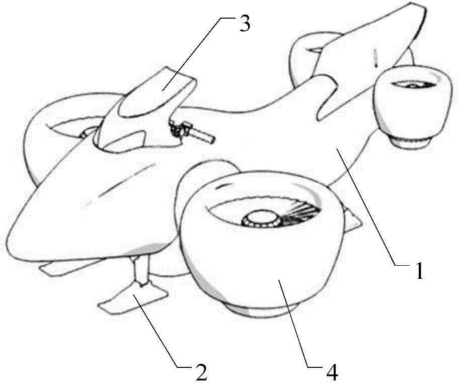
[0069] figure 1 It is a schematic diagram of embodiment 1. The flying motorcycle includes a fuselage 1, a fuselage bracket 2 installed at the bottom of the fuselage 1, an armrest 3 installed in front of the upper part of the fuselage 1, and a control system can be installed on the armrest 3 for controlling each The state of each part of the flying motorcycle. The flying motorcycle also includes a propeller 4 and a propeller driving device.

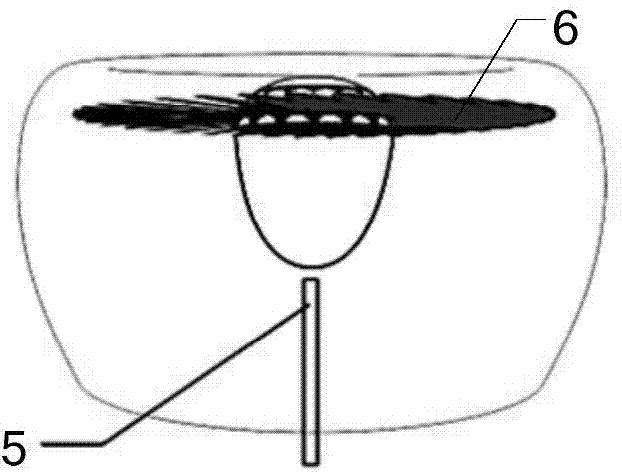
[0070] figure 2 It is a schematic diagram of the propeller of embodiment 1, the propeller 4 is a ducted turbofan engine, and a deflector 5 and a propeller 6 are installed inside, the deflector 5 is perpendicular to the horizontal plane, and is installed parallel to the fuselage 1, and the propeller 6 is parallel to the horizontal plane Install. In a propeller, one or more deflectors can be installed. When multiple deflectors are installed, the deflectors are parallel to each other. When the deflectors are in the offset state, The arra...

Embodiment 2

[0086] The flying motorcycle structure and propeller structure in embodiment 2 are all the same as embodiment 1, but deflectors are not installed inside the propeller in embodiment 2, so it is necessary to change the propeller driving device so that the propeller can not only Front and rear offsets, and left and right offsets can also be used to achieve the purpose of allowing the flying motorcycle to change its state freely.

[0087] Figure 20It is the schematic diagram of the thruster and the thruster driving device of embodiment 2. In this embodiment, the propeller driving device includes a ball shaft 11 and a hydraulic device 10. The ball shaft 11 is a ball end joint bearing, and one end is a universal ball joint bearing end, which can be fixed inside the fuselage of the flying motorcycle. And it can rotate freely in all directions, and the other end is a fixed end. The fixed end of the ball shaft 11 is connected to the side of the propeller 4, and the universal ball jo...

corresponding Embodiment 2

[0088] Corresponding to Embodiment 2, the corresponding method for adjusting the flying attitude of the flying motorcycle is as follows.

[0089] When the flying motorcycle needs to be in the hovering state, the propellers are kept vertical, the propeller rotates, and the flying motorcycle hovers in the air under the action of the propeller.

[0090] When it is necessary to keep the flying motorcycle in the forward state, the method of adjusting the state in Embodiment 1 is the same, the rear propeller is tilted towards the head of the fuselage, and the front propeller is kept vertical, then the propeller of the rear propeller will give A forward thrust of the flying motorcycle, pushing the flying motorcycle to fly forward.

[0091] When it is necessary to make the flying motorcycle be in the state of full speed forward, the state adjustment method in Embodiment 1 is the same, so that both the front thruster and the rear thruster are inclined towards the head of the fuselage, ...


PUM


Abstract

The invention discloses a flying motorcycle or automobile and a flight attitude adjustment method thereof. A flying motorcycle or automobile body is provided with a thruster and a thruster driving device. A propeller is mounted in the thruster. The thruster driving device controls rotation direction of the thruster. The thruster comprises a left front thruster body, a right front thruster body and a rear thruster body, wherein the left front thruster body and the right front thruster body are mounted on the left side and the right side of the front portion of the motorcycle or automobile body symmetrically, and the rear thruster body is mounted on the rear side of the motorcycle or automobile body. According to the flight attitude adjustment method, angle inclination of the thruster bodies mounted on the two sides and the rear portion of the flying motorcycle or automobile is driven by the thruster driving device to achieve turning, forward movement, backward movement, left translation and right translation of the flying motorcycle or automobile. The flying motorcycle or automobile can be always kept in a horizontal state during flight, can be applied to the field of manned flight and is quite wide in application range.

Description

technical field [0001] The invention relates to a small aircraft and an operation control method thereof, in particular to a flying motorcycle or automobile and a method for adjusting its flight attitude. Background technique [0002] Personal aircraft is a new application field of small aircraft. Most of the existing small aircraft are used to carry various measuring instruments for high-altitude detection or high-altitude object throwing. They can be used in various fields such as agriculture, detection, meteorology, disaster forecasting, and rescue. field. However, there are not many small aircraft that can carry people, and there is a lot of room for research. [0003] Existing aircraft is divided into two kinds of fixed-wing aircraft and multi-rotor aircraft. Fixed-wing aircraft generally use two methods of steering, one is purely by the vertical tail steering, and the other is the wing ailerons combined with the horizontal tail steering. Turning purely by the vertic...

Claims


Application Information

Patent Timeline
Patent Type & Authority Applications(China)
IPC IPC(8): B64C27/08B64C27/20B64C27/28
CPCB64C27/08B64C27/28
Inventor 陈乐春
Owner JIANGSU DIGITAL EAGLE TECH DEV
Learn More