Construction method, mounting structure and combined structure for coupling beam between shear wall limbs

A technology for installing structures and construction methods, applied to walls, building components, building structures, etc., can solve the problems of calculating additional internal forces, reducing the cross-sectional size of coupling beams, reducing the steel content of coupling beams, etc., to reduce the difficulty of design calculations, The effect of reducing the design and construction period and reducing the steel content

Active Publication Date: 2015-08-19
中国建筑东北设计研究院有限公司
View PDF5 Cites 1 Cited by
  • Summary
  • Abstract
  • Description
  • Claims
  • Application Information

AI Technical Summary

Problems solved by technology

[0004] The present invention mainly solves technical problems such as difficult calculation of additional internal force, complex construction, high cost and other technical problems caused by the difference in vertical deformation at both ends of the "hard-resistant" coupling beam in the prior art, and proposes a construction of coupling beams between shear wall limbs The method, installation structure and combined structure can release the additional internal force generated by the different vertical settlement at both ends of the coupling beam, reduce the cross-sectional size of the coupling beam, and reduce the steel content of the coupling beam

Method used


Image

  • Construction method, mounting structure and combined structure for coupling beam between shear wall limbs
  • Construction method, mounting structure and combined structure for coupling beam between shear wall limbs
  • Construction method, mounting structure and combined structure for coupling beam between shear wall limbs

Examples


Embodiment 1

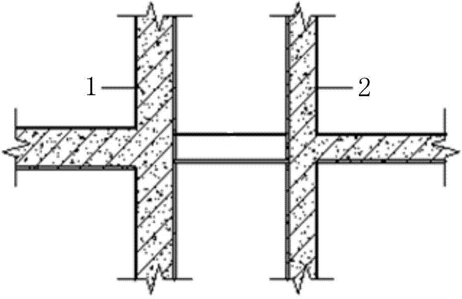
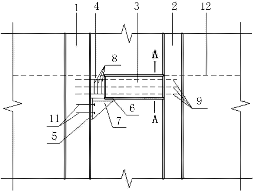
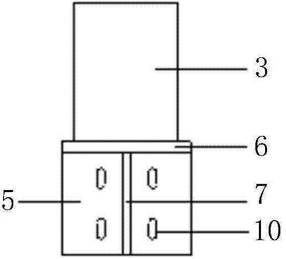
[0034] figure 1 It is a schematic diagram of the connection between the coupling beam and the shear wall pier. figure 2 It is a schematic diagram of the installation structure of the connecting beam between the shear wall piers. image 3 for along figure 2 A side sectional view in the direction of A-A. Such as figure 1 , 2 As shown in and 3, the present embodiment provides a mounting structure for connecting beams between shear wall limbs, including:

[0035] The connecting beam pouring section 3 and the steel support frame; the steel support frame includes a vertical plate 5, a horizontal steel plate 6 and a triangular rib plate 7, and the two right-angled sides of the triangular rib plate 7 are respectively fixedly connected with the vertical plate 5 and the horizontal steel plate 6, and the horizontal steel plate 6 Above the triangular rib 7, the riser 5 is used for fixed connection with the shear wall; one end of the connecting beam pouring section 3 is installed on...

Embodiment 2

[0040]This embodiment provides a combined structure of connecting beams between shear wall limbs, including a connecting beam and a steel support frame; the connecting beam is fixedly arranged between two shear wall limbs, and the steel supporting frame is arranged under the bottom surface of the connecting beam It is used to support the connecting beam, and the connecting beam is provided with stirrups and longitudinal steel bars; the steel support frame includes vertical plates, horizontal steel plates and triangular ribs, and the two right-angled sides of the triangular ribs are fixedly connected with the vertical plates and horizontal steel plates respectively, and the horizontal The steel plates are above the triangular ribs, and the vertical plates are used for fixed connection with the shear wall pier.

[0041] Wherein, the width of the horizontal steel plate is greater than the width of the coupling beam. Both sides of the horizontal steel plate are 50mm wider than the...


PUM


Abstract

The invention relates to the field of constructional engineering and provides a construction method, a mounting structure and a combined structure for a coupling beam between shear wall limbs. The construction method includes: burying anchor bolts in a shear wall limb on one side; fixing a steel support frame on the shear wall limb with the anchor bolt via anchor bolts and nuts; above the steel support frame, constructing stirrups and longitudinal reinforcement steel bars of the coupling beam; pouring concrete of the coupling beam to enable one end of the poured section of the coupling beam to be mounted on the shear wall limb without the steel support frame, enable the other end of the poured section of the coupling beam to overlap on the steel support frame and reverse a vertical seam between the poured section of the coupling beam and the shear wall limb with the steel support frame; after vertical differential settlement between each of two ends of the poured section of the coupling beam and the corresponding shear wall limb is smaller than 2-4mm, pouring concrete to the vertical seam to form an integral coupling beam. The construction method, the mounting structure and the combined structure have the advantages that additional internal force generated from vertical deformation difference between two ends of the coupling beam can be released, section size of the coupling beam can be decreased, and steel content of the coupling beam is decreased.

Description

technical field [0001] The invention relates to the field of construction engineering, in particular to a construction method, an installation structure and a combined structure of a connecting beam between limbs of a shear wall. Background technique [0002] At present, due to the diversification, individuation, and complexity of architectural design, in order to meet the building function and use requirements, the distance between two shear walls is often very close during structural design, and the vertical loads borne by these two shear walls are different. It is very large, so that the vertical deformation of the two shear wall piers under the vertical load is quite different, so the vertical deformation of the two ends of the connecting beams connecting the two shear walls is quite different, resulting in the connection Beams generate large additional internal forces. In order to meet the stability and rigidity requirements of the entire structure, the two ends of the...

Claims


Application Information

Patent Timeline
Patent Type & Authority Applications(China)
IPC IPC(8): E04G21/00E04G21/14E04B2/56
Inventor 陈鹏陈勇
Owner 中国建筑东北设计研究院有限公司
Why Eureka
Try Eureka