
Method for constructing connecting steel corridors

A technology of steel corridors and corridors, which is applied in the direction of construction, building structure, and building materials processing. It can solve the problems of overall structure vibration, unfavorable safety targets, and inability to ensure structural safety. It achieves simple and convenient fastening and releasing operations. Ease of construction

Active Publication Date: 2015-08-19
NO 1 CONSTR ENG CO LTD OF CHINA CONSTR THIRD ENG BUREAU CO LTD +2
View PDF4 Cites 10 Cited by
  • Summary
  • Abstract
  • Description
  • Claims
  • Application Information

AI Technical Summary

Problems solved by technology

[0006] 1) Using the direct cutting method, the operation is more difficult, and it is easy to cause safety accidents, which is not conducive to the control of safety objectives;
[0007] 2) The direct cutting method will cause a sudden change in the internal force of the structural member, which is not conducive to the safety of the structure; the connected body after cutting loses its bearing capacity, and cannot guarantee the safety of the structure in case of an accident;
[0008] 3) The direct cutting method will cause the vibration of the overall structure and have an adverse effect on the structure itself. If the measures are not taken properly, the safety of the structure cannot be guaranteed;
[0009] 4) The direct cutting method requires relevant preliminary preparations and supporting facilities, and the required labor and material costs are relatively high, which is not conducive to construction cost control
[0011] In summary, the above two schemes cannot meet the design requirements

Method used


Image

  • Method for constructing connecting steel corridors
  • Method for constructing connecting steel corridors
  • Method for constructing connecting steel corridors

Examples


Embodiment Construction

[0039] It should be understood that the specific embodiments described here are only used to explain the present invention, not to limit the present invention.

[0040] The invention proposes a construction method for connecting steel corridors.

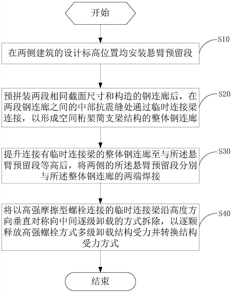
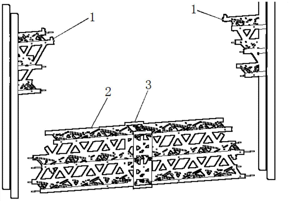
[0041] refer to figure 1 and figure 2 , figure 1 It is a schematic flow diagram of a preferred embodiment of the construction method of the connecting steel gallery of the present invention, figure 2 It is a structural schematic diagram of the connecting steel corridor of the present invention.

[0042] In this preferred embodiment, the construction method for connecting the steel gallery includes the following steps:

[0043] Step S10, install the cantilever reserved section 1 at the design elevation positions of the buildings on both sides;

[0044] Step S20, after pre-assembling two sections of steel corridors with the same cross-sectional size and structure, connect them through the temporary connecting beam 3 at the middl...


PUM


Abstract

The invention discloses a method for constructing connecting steel corridors. The method includes steps of mounting cantilever preserved sections at designed elevation positions of two side buildings; connecting middle anti-seismic joints between two steel connecting corridors by temporary connecting beams to form an integral steel connecting corridor with simply supported beam structures of spatial trusses after the two steel connecting corridors with identical sectional dimensions and structures are preliminarily assembled; lifting the integral steel connecting corridor connected with the temporary connecting beams until the elevation of the integral steel connecting corridor is equal to the elevation of the cantilever reserved sections, and respectively welding the cantilever reserved sections on two sides of the integral steel connecting corridor with the integral steel connecting corridor; perpendicularly symmetrically detaching the temporary connecting beams connected with the integral steel connecting corridor by high-strength frictional bolts towards the middle of the integral steel connecting corridor along the height direction of the integral steel connecting corridor in a step-by-step unloading mode, gradually releasing stress on multi-stage unloading structures in high-strength bolt modes and converting structure stress modes. The method for constructing the connecting steel corridors has the advantages that the construction difficulty can be lowered in procedures for constructing the connecting steel corridors, and the safety of the connecting steel corridors can be guaranteed.

Description

technical field [0001] The invention relates to the technical field of building construction, in particular to a method for building a connecting steel corridor. Background technique [0002] The construction of a large connecting corridor between two high-altitude buildings is different from a small connecting corridor bridge structure. The installation height of the connected structure is relatively high, the structure has a huge weight and has many components. If high-altitude bulk assembly is used, not only the workload of high-altitude assembly and welding is huge, but also there are great quality and safety risks. At the same time, the construction is difficult, which is not conducive to the overall implementation of the project. [0003] If high-altitude bulk assembly is used, due to the influence of the tower crane's lifting weight and operating radius, the assembled truss members are small, and high-altitude installation and welding are difficult, and the installati...

Claims


Application Information

Patent Timeline
Patent Type & Authority Applications(China)
IPC IPC(8): E04G21/14
Inventor 胥超明郭福元姚澄毛岳清陈和姜龙华
Owner NO 1 CONSTR ENG CO LTD OF CHINA CONSTR THIRD ENG BUREAU CO LTD
Learn More