A kind of z-pin reinforced composite wind power blade structure and manufacturing method thereof

A technology for reinforcing composite materials and wind turbine blades, applied in the field of composite material reinforcement, can solve the problems of insufficient performance of the blade shell, weak bearing capacity of open thin-walled beams, poor connection interface performance, etc., and achieve strong designability and easy integration Strong molding and anti-peeling properties

Active Publication Date: 2017-11-03
NANJING UNIV OF AERONAUTICS & ASTRONAUTICS
View PDF10 Cites 0 Cited by
  • Summary
  • Abstract
  • Description
  • Claims
  • Application Information

AI Technical Summary

Problems solved by technology

Since the strength of the bonding part is far lower than the strength of the shell itself, the performance of the blade shell cannot be fully utilized, and the load-bearing capacity of the thin-walled beam similar to the opening is very weak, which leads to the structure of the upper and lower half shells and the main beam of the wind turbine blade. The performance of the connection interface is poor, and the problem of low peeling resistance

Method used


Image

  • A kind of z-pin reinforced composite wind power blade structure and manufacturing method thereof
  • A kind of z-pin reinforced composite wind power blade structure and manufacturing method thereof
  • A kind of z-pin reinforced composite wind power blade structure and manufacturing method thereof

Examples


Embodiment 1

[0036] Embodiment 1: A method for manufacturing a Z-pin reinforced composite wind turbine blade structure of the present invention, the method includes the following steps:

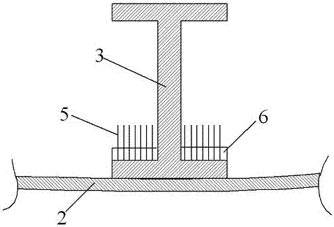
[0037] Step 1: Prepare high-performance Z-pin5 through advanced pultrusion equipment, design Z-pin5 parameters, and then implant Z-pin5 into foam preform 6;

[0038]Step 2: Lay the main girder 3 of the composite material on the special mold according to the designed laying sequence and the number of layers;

[0039] Step 3: Lay the upper half blade shell 1 in the upper mold of the wind power blade, lay the lower half blade shell 2 in the lower mold of the wind power blade, and then place the above-mentioned main girder 3 on the lower half blade The predetermined position of the casing 2 is such that the lower surface of the lower edge of the main beam 3 is in close contact with the inner wall of the lower half-blade casing 2, thereby forming a lower joint surface;

[0040] Step 4: Bending the above-menti...

Embodiment 2

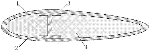
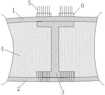
[0050] A Z-pin reinforced composite material wind power blade structure of the present invention includes an upper half blade shell 1 and a lower half blade shell 2 that cooperate to form a blade cavity and are located in the blade cavity for bearing most of the wind power blade. The I-shaped main beam 3 of the bending load, the upper edge of the I-shaped main beam 3 is closely attached to the inner wall of the upper half blade shell 1 to form an upper joint surface, and the lower edge of the I-shaped main beam 3 and the lower The inner walls of the half-blade shell 2 are tightly matched to form a lower joint surface, and the joints of the upper joint surface and the joint of the lower joint surface are implanted with pinning bridges to improve the main beam 1 and the upper half-blade shell. 1 and the Z-pin5 of the connection strength between the I-shaped main beam 3 and the lower half of the blade shell 2, the blade cavity is filled with fillers on both sides of the I-shaped m...


PUM


Abstract

The invention discloses a Z-pin reinforced composite material wind power blade structure. The Z-pin reinforced composite material wind power blade structure comprises an upper half blade shell, a lower half blade shell and a main beam, wherein the upper half blade shell and the lower half blade shell are matched to form a blade cavity, the upper edge of the main beam and the inner wall of the upper half blade shell are tightly attached to form an upper connecting surface, the lower edge of the main beam and the inner wall of the lower half vane shell are tightly attached to form a lower connecting surface, Z-pins which have pinning and bridging functions and improve the connecting strength between the main beam and the upper half blade shell as well as between the main beam and the lower half blade shell are arranged at the connecting positions of the upper connecting surface and the lower connecting surface, and the part, located on two sides of the main beam, of the blade cavity is filled with foam. The Z-pin reinforced composite material wind power blade structure can obviously improve the layered rigidity of composite material laminated wood. A manufacturing method is simple. The Z-pin reinforced composite material wind power blade structure is high in designability, is easy to form overall and further has the advantages of being good in weight-reducing property, resistant to shearing, high in stripping resistance and small in damage to fibers.

Description

technical field [0001] The invention relates to the technical field of composite material reinforcement, in particular to a Z-pin reinforced composite material wind power blade structure and a manufacturing method thereof. Background technique [0002] Wind turbine blades are the key components of energy conversion in wind turbines, and they are also the most complex components. The quality of their design and manufacture is directly related to the efficiency and service life of wind turbines, and affects the performance of the entire system. Among them, composite wind turbines Blades are being used more and more widely because of their light weight, high strength, designability, good load-carrying performance, and good fatigue performance. From the perspective of blade manufacturing technology, the current large and medium-sized fan blades basically adopt the structure of skin and main beam, and are prepared through a multi-step molding process, that is, the upper and lower...

Claims


Application Information

Patent Timeline
Patent Type & Authority Patents(China)
IPC IPC(8): F03D1/06B29C70/34
CPCY02E10/72Y02P70/50
Inventor 还大军李勇李吻肖军
Owner NANJING UNIV OF AERONAUTICS & ASTRONAUTICS
Why Eureka
Try Eureka