
Fiber-reinforced resin, process for producing same, and molded article

a fiber reinforced resin and fiber reinforcement technology, applied in the field of fiber reinforced resin, can solve the problems of difficult handling and insufficient improvement of the reinforcing effect of polyamide particles, and achieve the effects of improving the interlaminar toughness of the cfrp, improving the reinforcing effect, and easy handling

Active Publication Date: 2019-02-14
DAICEL EVONIK LTD
View PDF0 Cites 0 Cited by
  • Summary
  • Abstract
  • Description
  • Claims
  • Application Information

AI Technical Summary

Benefits of technology

The present invention provides a resin composition by combining a resin particle with a carbon fiber and a matrix resin. This results in improved strength and durability of the resin. The process for producing the resin involves simple impregnation of the resin particle with the matrix resin and reinforcing fiber. This improves the interlaminar toughness of the resulting composite material, making it easier to handle.

Problems solved by technology

Unfortunately, these polyamide particles fail to sufficiently improve a reinforcing effect by the reinforcing fiber.
Further, the polyamide particles described in Patent Document 2, which contain two kinds of polyamide particles, need homogeneous mixing, and this results in difficult handling.

Method used


Image

  • Fiber-reinforced resin, process for producing same, and molded article
  • Fiber-reinforced resin, process for producing same, and molded article
  • Fiber-reinforced resin, process for producing same, and molded article

Examples


example 1

[0148](Production of Resin Particle)

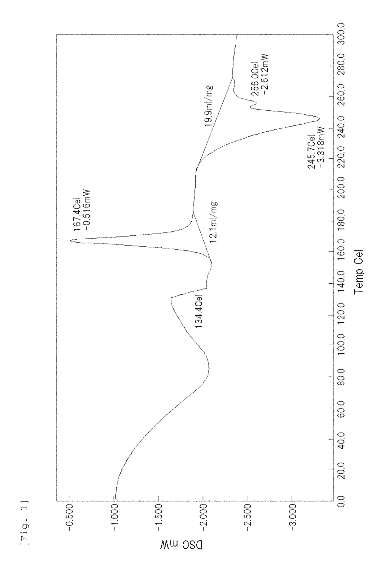
[0149]The alicyclic PA was shaped into a fine particulate form by forced emulsification using a poly(ethylene glycol) in accordance with Examples of Japanese Patent Application Laid-Open Publication No. 2010-132811. A melt-kneaded product containing an alicyclic PS and a poly(ethylene glycol) extruded from a die of an extruder was forcibly cooled by a spot cooler and then washed with water for removal of only the poly(ethylene glycol). The washed product was dried at a temperature of 120° C. for 24 hours under a reduced pressure to give a resin particle (powder). The resin particle had an average particle size of 21 μm and had a crystallization peak observed under a heating condition of 10° C. / min. by DSC. The DSC chart (heat absorption curve) is shown in FIG. 1. As apparent from FIG. 1, a high peak by crystallization is observed around 170° C., and the degree of crystallinity is also low. The results show that the obtained particle has a low crys...

example 2

[0160]A test piece was produced in the same manner as Example 1 except for the following: in the production of the resin particle, the PA12 and a saccharide were used instead of the alicyclic PA and the poly(ethylene glycol), the melt-kneaded product was allowed to cool without using the spot cooler, and after removal of the saccharide the resulting product was dried by heating at 80° C. for 3 hours without drying under a reduced pressure. The resin particle had an average particle size of 20 μm and had a crystallization peak observed under a heating condition of 10° C. / min. by DSC. The DSC chart (heat absorption curve) is shown in FIG. 4. As apparent from FIG. 4, a peak by crystallization is observed around 170° C. FIG. 5 is a wide-angle X-ray diffraction chart. As apparent from FIG. 5, the X-ray spectrum of the obtained PA12 particle has one peak at 20 of 21.5°, which shows that the PA12 particle has a γ-type crystal structure.

example 3

[0162]A test piece was produced in the same manner as Example 1 except for the following: in the production of the resin particle, the PA1010 and a saccharide were used instead of the alicyclic PA and the poly(ethylene glycol), the melt-kneaded product was allowed to cool without using the spot cooler, and after removal of the saccharide the resulting product was dried by heating at 80° C. for 3 hours without drying under a reduced pressure. The resin particle had an average particle size of 22 μm and had a crystallization peak observed under a heating condition of 10° C. / min. by DSC. FIG. 8 is a wide-angle X-ray diffraction chart. As apparent from FIG. 8, the X-ray spectrum of the PA1010 particle obtained in Example 3 has two peaks at 20 of 20.4° and 20 of 23.6°, which shows that the PA1010 particle has an α-type crystal structure.


PUM

PropertyMeasurementUnit
particle sizeaaaaaaaaaa
melting pointaaaaaaaaaa
glass transition temperatureaaaaaaaaaa

Abstract

(A) A reinforcing fiber, (B) a resin particle, and (C) a matrix resin are combined to prepare a resin composition which improves a reinforcing effect by the reinforcing fiber. The reinforcing fiber (A) contains a carbon fiber. The resin particle (B) contains a semicrystalline thermoplastic resin, the semicrystalline thermoplastic resin in the resin particle (B) has an exothermic peak in a temperature range between a glass transition temperature of the semicrystalline thermoplastic resin and a melting point of the semicrystalline thermoplastic resin, the peak being determined by heating the resin particle (B) at a rate of 10° C. / min. by differential scanning calorimetry (DSC), and the resin particle (B) has an average particle size of 3 to 40 μm. The semicrystalline thermoplastic resin may be a polyamide resin having a melting point of not lower than 150° C. (particularly, a polyamide resin having an alicyclic structure and a glass transition temperature of not lower than 100° C., or a polyamide resin having a γ-type crystal structure or a degree of crystallinity of not more than 50%). The matrix resin (C) may be a thermosetting resin.

Description

CROSS-REFERENCE TO RELATED APPLICATIONS[0001]This application is a Continuation of co-pending application Ser. No. 15 / 759,976 filed on Mar. 14, 2018, which is a National Phase of PCT International Application No. PCT / JP2016 / 079689 filed on Oct. 5, 2016, which claims priority under 35 U.S.C. § 119(a) to Patent Application No. 2015-199751 filed in Japan on Oct. 7, 2015. All of the above applications are hereby expressly incorporated by reference into the present application.TECHNICAL FIELD[0002]The present invention relates to resin compositions containing reinforcing fibers, processes for producing the same, and molded articles (or fiber-reinforced composites) containing the resin compositions.BACKGROUND ART[0003]Carbon-fiber-reinforced plastics (CFRPs), which contains carbon fibers and matrix resins, have excellent strength, stiffness, or other characteristics and are used for various applications, for example, primary structure members of flying machines, automotive members, windmi...

Claims


Application Information

Patent Timeline
Patent Type & Authority Applications(United States)
IPC IPC(8): C08J5/04C08J3/12B29B11/16C08J5/10C08J5/24
CPCC08J5/042C08J3/12C08J2377/00B29B11/16C08J5/10C08J5/24C08J2300/24C08K7/06C08J2400/00C08J5/243C08G59/1472C08L63/00C08J2363/00C08G69/14C08G69/26C08K3/04C08K7/02C08L23/26C08L77/00C08K7/04C08L71/02
Inventor MUTSUDA, MITSUTERUNAKAIE, YOSHIKIUNO, TAKAYUKI
Owner DAICEL EVONIK LTD
Learn More