Air duct flow measuring system

A flow measurement and intake port technology, applied in the field of intake port flow measurement systems, can solve the problems of complex flow matching and aerodynamic interference in the intake port, strong aerodynamic interference, and inability to simulate the coupling characteristics of the intake port. The effect is good, the integrity is good, and the components are easy to assemble and disassemble.

Active Publication Date: 2015-08-19
CHINA ACAD OF AEROSPACE AERODYNAMICS
View PDF4 Cites 46 Cited by
  • Summary
  • Abstract
  • Description
  • Claims
  • Application Information

AI Technical Summary

Problems solved by technology

[0005] In addition, for the dual inlets of the ramjet/turbo engine type, there will be strong aerodynamic interference between the inlets, especially when the engine is in mode transition, the inlet of the turbine engine inlet is gradually closed, and the

Method used


Image

  • Air duct flow measuring system
  • Air duct flow measuring system
  • Air duct flow measuring system

Examples


Embodiment Construction

[0029] The present invention will be further introduced below in conjunction with the accompanying drawings.

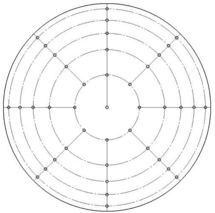
[0030] Such as figure 1 As shown, the intake port flow measurement system of the present invention includes a housing 1, a throttle cone 2, a servo motor 3, a feedback device 4, a damping net 5, a honeycomb 6, a total pressure measurement rake 7, a Laval nozzle 8 and The static pressure measuring device 9 has a cylindrical housing 1 with an interface at its front end, which can be sealed and connected to the outlet of the air inlet test model through a medium-pressure rubber hose in the laboratory. At the rear end of the interface there is a flared section for decelerating the incoming flow, followed by a straight section. The throttling cone 2 is arranged in the expansion section, and the servo motor 3 and the feedback device 4 are arranged in the straight section of the housing 1 . The throttling cone 2, the servo motor 3 and the feedback device 4 together constit...


PUM

PropertyMeasurementUnit
Diagonal lengthaaaaaaaaaa
Lengthaaaaaaaaaa
Total lengthaaaaaaaaaa

Abstract

The invention discloses an air duct flow measuring system. The air duct flow measuring system comprises a shell, a reverse pressure adjusting device, a rectifying device, a total pressure measurement rake, a Laval spraying tube and a static pressure measuring device, wherein the shell is cylindrical; a connector is arranged at the front end of the shell; an expansion section is arranged at the rear end of the connector and is used for reducing the speed of incoming flow; a straight section is arranged behind the expansion section; the reverse pressure adjusting device comprises a throttling cone and a driving control mechanism; the throttling cone is arranged in the expansion section; the driving control mechanism is arranged in the straight section; the rectifying device, the total pressure measurement rack and the Laval spraying tube are sequentially arranged in the straight section and behind the driving control mechanism; an outlet of the Laval spraying tube is parallel and level to a rear end opening of the shell; and the static pressure measuring device is arranged at the throat of the Laval spraying tube. By the air duct flow measuring system, reverse pressure of an outlet of the double-spraying air duct can be adjusted in real time, the flow of air flowing into the double-spraying air duct can be measured accurately, and the air flowing in the air duct can be sucked according to specific test conditions so as to increase the flow of the air and meet requirements of a test on the air duct.

Description

technical field [0001] The invention relates to a high-precision intake duct flow measurement system with a suction function, which can be well applied to adjust the back pressure of the intake duct exit and accurately measure the intake duct exit in the double-engine intake duct test of a high-speed wind tunnel If necessary, use the suction device to increase the main gas flow of the intake port to obtain and evaluate the aerodynamic performance of the intake port. Background technique [0002] The air intake is a key part of the air-breathing aircraft. It is a well-designed airflow channel, which is used to introduce air. After decelerating and boosting the airflow, it is provided to the engine combustion chamber. Affect the overall performance of the engine and even the aircraft. [0003] Inlet wind tunnel test is the main means to evaluate the performance of the inlet and obtain the characteristic parameters of the inlet. The flow coefficient is the ratio of the actual...

Claims


Application Information

Patent Timeline
IPC IPC(8): G01F1/88G01M9/06
Inventor 欧平童木华沈林强田晓虎陈强秦永明
Owner CHINA ACAD OF AEROSPACE AERODYNAMICS
Why Eureka
Try Eureka