Solar cell structure

A solar cell and electrode technology, applied in the field of solar cells, can solve the problems of low photoelectric conversion efficiency of ordinary solar cells

Active Publication Date: 2015-08-19
嘉兴巨腾信息科技有限公司
View PDF3 Cites 5 Cited by
  • Summary
  • Abstract
  • Description
  • Claims
  • Application Information

AI Technical Summary

Problems solved by technology

[0008] In order to solve the problem of low photoelectric conversion efficiency of existing ordinary solar cells, the present invention provides a solar cell structure in which the first electrode and the second electrode arranged on the left and right in the ordinary solar cell structure are changed to the first electrode and the second electrode arranged in the center of the ferroelectric material. An electrode and a second electrode arranged on the edge of the ferroelectric material, and the second electrode at least partially surrounds the first electrode, leaving a distance between the first electrode and the second electrode

Method used


Image

  • Solar cell structure
  • Solar cell structure
  • Solar cell structure

Examples


Embodiment Construction

[0024] The present invention will be further described below in conjunction with drawings and embodiments.

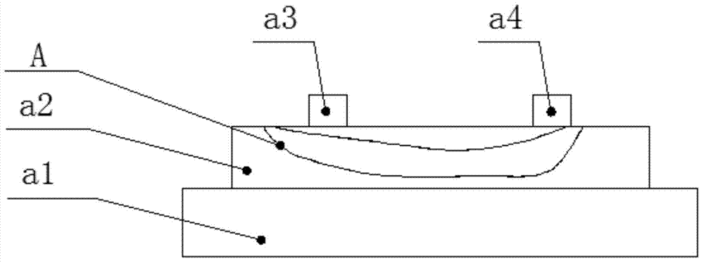
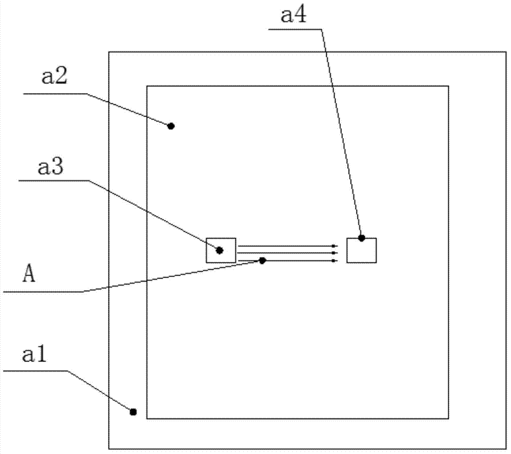
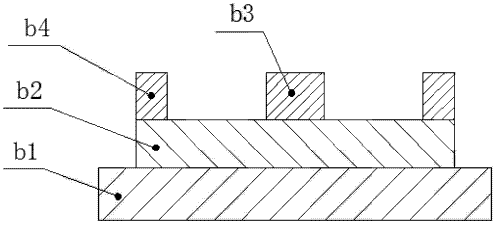
[0025] Such as image 3 with Figure 4 As shown, a solar cell structure includes a substrate b1, a ferroelectric material b2 is grown on the substrate b1; a first electrode b3 and a second electrode b4 are grown on the ferroelectric material b2, and the first The electrode b3 is arranged at the center of the ferroelectric material b3, and the second electrode b4 is arranged at the edge of the ferroelectric material b2; the second electrode b4 at least partially surrounds the first electrode b3, and the first electrode b3 and the second electrode b4 Leave a distance between them.

[0026] The second electrode b4 is arranged around the first electrode b3 and extends to surround the first electrode b3.

[0027] In this embodiment, the second electrode b4 is provided with a circular relief hole; the first electrode b3 is circular, the first electrode b3 is set in the rel...


PUM


Abstract

The invention discloses a solar cell structure which comprises a substrate, wherein a ferroelectric material grows on the substrate, a first electrode and a second electrode grow on the ferroelectric material, the first electrode is arranged at the center of the ferroelectric material, the second electrode is arranged at the edge of the ferroelectric material, the second electrode at least partially encloses the first electrode, and a distance is reserved between the first electrode and the second electrode. A circular demising hole is formed in the second electrode, the first electrode is arranged at the center of the demising hole, and the first electrode is circular. An electric field in the ferroelectric material is radially diverged from the first electrode to the second electrode. Compared with a common solar cell structure that the electric field is uniformly distributed and is vertical to the two electrodes, the solar cell structure disclosed by the invention has the advantages that the electric field is radially diverged from the first electrode to the second electrode, a voltage enclosed by the electric field is remarkably increased, so that a number of carriers separated by the electric field is increased, and finally the effect of enhancing a photovoltaic effect is achieved.

Description

technical field [0001] The invention belongs to the field of solar cells, and in particular relates to a solar cell structure. Background technique [0002] Such as figure 1 with figure 2 In the common solar cell structure shown, a ferroelectric material a2 is grown on the substrate a1, a first electrode a3 and a second electrode a4 are grown on the ferroelectric material a2, and the first electrode a3 and the second electrode a4 are arranged on the ferroelectric On the left and right sides of the material a2, the areas of the first electrode a3 and the second electrode a4 are relatively small, for example, a square with a side length of 200 μm˜600 μm. In such a scale, after the ferroelectric material is polarized by an external electric field, a depolarization field will be generated between the first electrode a3 and the second electrode a4. Since the side lengths of the first electrode a3 and the second electrode a4 are generally much larger than the distance between ...

Claims


Application Information

Patent Timeline
IPC IPC(8): H01L31/0224H01L31/18
CPCH01L31/0224H01L31/022425Y02E10/50Y02P70/50
Inventor 高荣礼符春林蔡苇邓小玲陈刚
Owner 嘉兴巨腾信息科技有限公司
Why Eureka
Try Eureka