Hybrid direct-current transmission system, control method and power reversal control method

A power transmission system and hybrid DC technology, applied in power transmission and AC networks, etc., can solve the problems of inability to change the polarity of the DC voltage, incapable of making full use of the converter, and inability to change the current direction, achieving low loss, high reliability, less dependent effect

Active Publication Date: 2015-08-19
NR ELECTRIC CO LTD +1
View PDF6 Cites 26 Cited by
  • Summary
  • Abstract
  • Description
  • Claims
  • Application Information

AI Technical Summary

Problems solved by technology

This system combines the advantages of traditional DC transmission with low loss, mature operation technology and flexible DC transmission that can supply power to the passive network without commutation failure. control, such as figure 1 In the system shown, if one thyristor converter fails, the power delivery of the entire system will be interrupted due to the lack of current path
Since the traditional DC converters all use thyristor converters, the current direction cannot be changed, and only the voltage polarity can be changed when the po...

Method used


Image

  • Hybrid direct-current transmission system, control method and power reversal control method
  • Hybrid direct-current transmission system, control method and power reversal control method
  • Hybrid direct-current transmission system, control method and power reversal control method

Examples


Embodiment 1

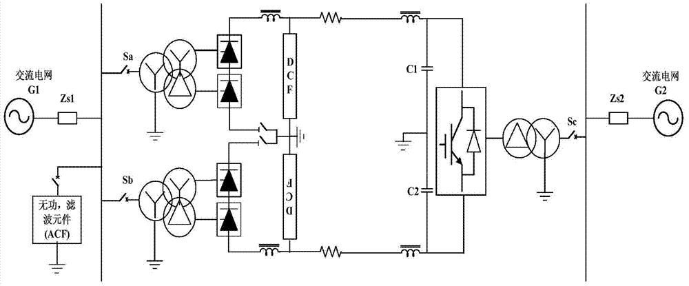
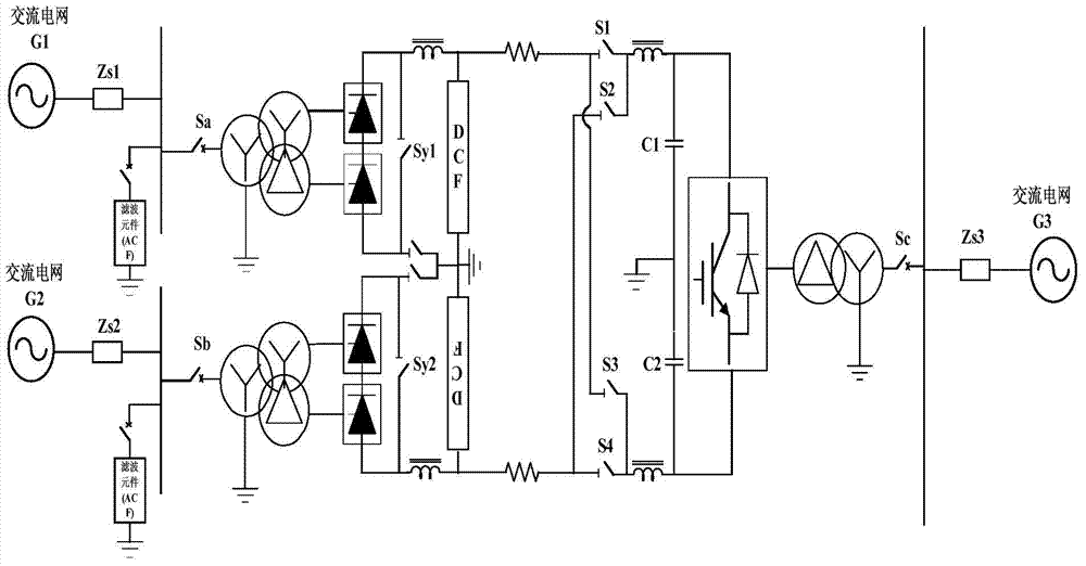
[0037] see image 3 , a hybrid DC power transmission system, including a sending-end converter station for connecting to the sending-end AC grid, a receiving-end converter station for connecting to the receiving-end AC grid, and a sending-end converter station and a receiving-end converter station for connecting The DC transmission line of the rectifier station; it is characterized in that: the sending-end converter station is a rectifying converter station, and the receiving-end converter station is an inverting converter station; the rectifying-converting station is used to connect the three After the phase alternating current is converted into direct current, it is transmitted to the inverter converter station through the direct current transmission line; the inverter converter station is used to convert the direct current into three-phase alternating current and transmit it to the receiving end AC power grid; the rectifier converter station includes phase-series The first ...

Embodiment 2

[0047] Such as image 3 As shown, the first group of thyristor converter units and the second group of thyristor converter units connected in series are respectively connected to AC grid G1 and AC grid G2; The AC grid G1 has excess power, and at the same time, the AC grid G2 has a power shortage. At this time, the first switch element S1 can be closed, the second switch element S2 can be closed, the third switch element S3 can be opened, and the fourth switch element S4 can be opened to form a second switch. One current path, the power is transmitted from the AC grid G1 to the AC grid G2; at this time, the first group of thyristor converter units is a rectifier unit; the second group of thyristor converter units is an inverter unit, and the active power is transferred from the first group of thyristors The AC grid G1 connected to the converter unit is transmitted to the second group of thyristor converter units through the first group of thyristor converter units, the first sw...

Embodiment 3

[0051] The hybrid direct current transmission system control method includes the following steps:

[0052] According to operation needs, operate the first switching element S1, the second switching element S2, the third switching element S3, and the fourth switching element (S4), forming the first group of thyristor converter units and the second group of thyristor converter units A first power transmission system composed of units, and forming a second power transmission system composed of the voltage source converter and at least one group of thyristor converter units;

[0053]The first group of thyristor converter units and the second group of thyristor converter units are connected to different AC grids; the first switch element S1 is closed and the second switch element S2 is closed, and the third switch element S3 is open and the fourth switch The element S4 is turned off to form a first current path; or the first switch element S1 is turned off and the second switch ele...


PUM


Abstract

The invention discloses a hybrid direct-current transmission system. A first group of thyristor converter units and a second group of thyristor converter units are connected with the same sending end alternating-current power grid through a converter respectively, or connected with different sending end alternating-current power grids. An inversion converter station is composed of at least one group of voltage source converters, direct-current lines at the positive and negative ends of each voltage source converter are respectively equipped with a first switching element and a fourth switching element, and the direct-current lines at the positive and negative ends are wired in parallel and in a cross manner to the opposite-end direct-current lines through the first switching element and the fourth switching element respectively. Converter stations at the two ends are connected by two direct-current lines. The invention further discloses a hybrid direct-current transmission system control method and a hybrid direct-current transmission system power reversal control method. The hybrid direct-current transmission system of the invention has the advantages of low cost of traditional direct current, flexible control on flexible direct current, and the like.

Description

technical field [0001] The invention relates to the field of hybrid direct current transmission, in particular to a hybrid direct current transmission system, a control method and a power flow reversal control method. Background technique [0002] HVDC transmission systems can be divided into two types: traditional DC transmission systems (LCC-HVDC) based on thyristor technology; flexible HVDC systems based on fully controlled power electronic device technology (Flexible-HVDC). The traditional direct current transmission system (LCC-HVDC) has low cost, low loss, and mature operation technology. At present, almost all the operating direct current transmission systems in the world are LCC-HVDC systems, but the traditional direct current transmission system (LCC-HVDC) has inverter It is prone to commutation failure, strong dependence on the AC system, absorbs a large amount of reactive power, and the converter station occupies a large area. The new generation of flexible direc...

Claims


Application Information

Patent Timeline
IPC IPC(8): H02J3/36
CPCY02E60/60
Inventor 赵文强王永平李海英王俊生汪楠楠杨建明胡兆庆柏传军
Owner NR ELECTRIC CO LTD
Why Eureka
Try Eureka