
Method for measuring fresh air by evaluating internal cylinder pressure signal

A cylinder and air quality technology, applied in electrical control, machine/engine, engine control, etc., can solve problems such as the complexity of the engine control system

Active Publication Date: 2015-08-19
VTESCO TECH GMBH
View PDF7 Cites 4 Cited by
  • Summary
  • Abstract
  • Description
  • Claims
  • Application Information

AI Technical Summary

Problems solved by technology

[0006] To measure the fresh air in the cylinders in this way using the measured value of the filling and using the filling equivalent necessarily requires a complex model (especially because of the many parameters necessary) which would make the engine control system extremely complex
In addition, many additional sensors are necessarily required

Method used


Image

  • Method for measuring fresh air by evaluating internal cylinder pressure signal
  • Method for measuring fresh air by evaluating internal cylinder pressure signal
  • Method for measuring fresh air by evaluating internal cylinder pressure signal

Examples


Embodiment Construction

[0085] The same or similar parts are indicated by the same reference symbols in the figures. The illustrations in the figures are schematic and not to scale.

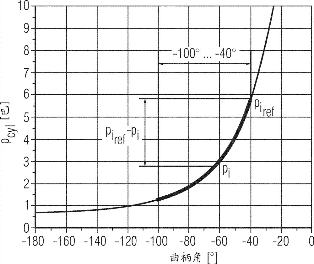
[0086] figure 1 shows the total gas mass m in the cylinder of the internal combustion engine during the compression phase Cyl pressure curve. Crank angles between -180° and 0° are indicated on the X-axis. Between -180° and 0° crank angle there is a portion of the cylinder's intake phase and compression phase. For example, up to a crank angle of 110°, a gas mixture such as, for example, air and / or fuel is drawn in, and from 110° onwards the inlet valve is closed. Subsequently, between a crank angle of 110° and a crank angle of 0°, the compression work starts, where the piston in the cylinder causes the total gas mass m in the cylinder to Cyl compression.

[0087] exist figure 1 In the example in , the first angular range for determining the crank angle in the compression phase is between approximately 100° and -40...


PUM


Abstract

The invention relates to a method for determining an air mass mair in a cylinder of an internal combustion engine. A first filling equivalent FAcomp is determined during a compression phase of the cylinder, wherein the first filling equivalent corresponds to a first average pressure difference in a first angle range of a crank angle in the compression phase. A second filling equivalent FAexp is determined during an expansion phase of the cylinder, wherein the second filling equivalent corresponds to a second average pressure difference in a second angle range of the crank angle of the expansion phase. A differential filling equivalent FAdiff is calculated by subtracting the first filling equivalent from the second filling equivalent. The air mass in the cylinder is determined on the basis of the differential filling equivalent. The invention further relates to a corresponding control device and to a corresponding computer program for performing said method.

Description

technical field [0001] The invention relates to a method for determining the air mass in a cylinder of an internal combustion engine. Furthermore, the invention relates to a method for operating an internal combustion engine and a control device for an internal combustion engine. Background technique [0002] There is a desire to improve internal combustion engines operating on fossil fuels in order to reduce emission limits and fuel consumption. As a result, the mechanical design of internal combustion engines continues to become more complex. Specifically, the efficiency of internal combustion engines can be improved by feeding air mass into the cylinders. Depending on the engine design, for example, a complex camshaft adjustment system for adjusting the stroke and phase of the inlet and outlet valves can be controlled in such a way that the filling losses of the cylinders are reduced. For example, it is also possible to actuate the inlet and outlet valves of the indivi...

Claims


Application Information

Patent Timeline
IPC IPC(8): F02D35/02
CPCF02D2200/0402F02D41/009F02D41/182F02D35/023
Inventor H.许勒B.克诺尔
Owner VTESCO TECH GMBH
Learn More