Sealing ring for pressure control valve

A technology of pressure regulation and sealing ring, applied in the field of pressure regulating valve, can solve the problems of unsatisfactory shape stability of sealing ring, shortened service life, leakage and so on

Active Publication Date: 2015-08-19
ELRINGKLINGER AG
View PDF6 Cites 3 Cited by
  • Summary
  • Abstract
  • Description
  • Claims
  • Application Information

AI Technical Summary

Problems solved by technology

However, the disadvantage of these materials is that the shape stability of the sealing rings made of them is not ideal at very low temperatures as well as at very high temperatures, whereby leakage may occur
In addition, elastomeric seals are subject to relatively high material wear, which shortens their service life accordingly

Method used


Image

  • Sealing ring for pressure control valve

Examples


Embodiment Construction

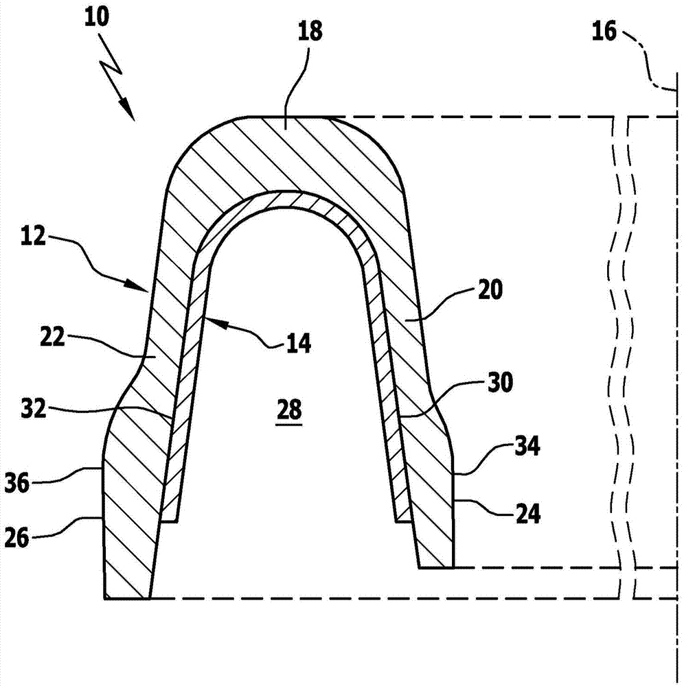
[0035] figure 1 A schematic cross-sectional view of an embodiment of a sealing ring according to the invention, generally designated 10 , is shown. The sealing ring 10 consists of two parts, namely, a sealing body 12 made of a material having one or more perfluorinated thermoplastics as main components and a spring element 14 made of steel, wherein the two The parts 12 and 14 are formed rotationally symmetrically with respect to the cylinder axis 16 .

[0036] The sealing body 12 has a substantially U-shaped cross-sectional profile with a top region 18 and two sealing lips 20 and 22 , which extend from the top region 18 approximately along the cylinder axis 16 with an opening angle of approximately 15°. direction extension. In this case, the inner sealing lip 20 facing the cylinder axis 16 has an inner sealing surface 24 , and the sealing lip 22 facing away from the cylinder axis 16 has an outer sealing surface 26 . When the sealing ring 10 is fixed on the valve cylinder in...


PUM


Abstract

The present invention relates to a sealing ring (10) for a pressure control valve for controlling the charge pressure in an internal combustion engine with a turbocharger, comprising • - a sealing body (12) which is rotationally symmetrical with respect to a cylinder axis (16) and is made of a material which comprises as main constituent one or more perfluorinated thermoplastics, wherein the sealing body (12) has a substantially U-shaped cross-sectional profile with an apex region (18) and two sealing lips (20, 22) which, starting from the apex region (18), extend parallel to one another or with an opening angle at least approximately in the direction of the cylinder axis (16); and • - a spring element (14) which is rotationally symmetrical with respect to the cylinder axis (16) and is made of steel and has a substantially U-shaped cross-sectional profile, wherein the spring element (14) is arranged between the sealing lips (20, 22) of the sealing body (10) in such a way that it bears directly against the mutually facing surfaces (30, 32) thereof.

Description

technical field [0001] The invention relates to a sealing ring for a pressure regulating valve for controlling the charging pressure in an internal combustion engine with a turbocharger. [0002] The invention also relates to a pressure regulating valve for controlling the charging pressure in an internal combustion engine with a turbocharger, which pressure regulating valve comprises such a sealing ring. Background technique [0003] In internal combustion engines equipped with a turbocharger for compressing the air supplied to the cylinders, in particular gasoline or diesel engines of motor vehicles, the boost pressure depends primarily on the ambient air pressure and the rotational speed of the turbocharger. In order to be able to control the boost pressure according to the corresponding power requirement of the engine, a pressure regulating valve is usually provided. The pressure regulating valve comprises a valve piston which is displaceably arranged in the valve cylin...

Claims


Application Information

Patent Timeline
Patent Type & Authority Applications(China)
IPC IPC(8): F16J15/32
CPCF16J15/3212F16J15/3236F02B37/16F16J15/3284F16K17/04F16K25/00
Inventor 京特·格劳马丁·迈尔穆罕默德·灿卡尔
Owner ELRINGKLINGER AG
Why Eureka
Try Eureka