
Back plate engraving die

A mold and backplane technology, applied in the field of backplane imprinting molds, can solve problems such as complex procedures, low processing efficiency, and high manufacturing costs, and achieve the effects of accurate product dimensions, improved efficiency, and guaranteed bending quality

Inactive Publication Date: 2015-08-26
昆山电子羽电业制品有限公司
View PDF7 Cites 5 Cited by
  • Summary
  • Abstract
  • Description
  • Claims
  • Application Information

AI Technical Summary

Problems solved by technology

Therefore, not only the manufacturing cost of the mold is high, the process is relatively complicated, and the processing efficiency is extremely low. Due to the need to disassemble the product multiple times and position the product multiple times at the same time, the error increases, which greatly affects the accuracy of the product.
It cannot meet the increasingly high requirements of modern industrial production for the production of molds for such products

Method used


Image

  • Back plate engraving die

Examples


Embodiment Construction

[0020] The present invention will be described in detail below in conjunction with the accompanying drawings.

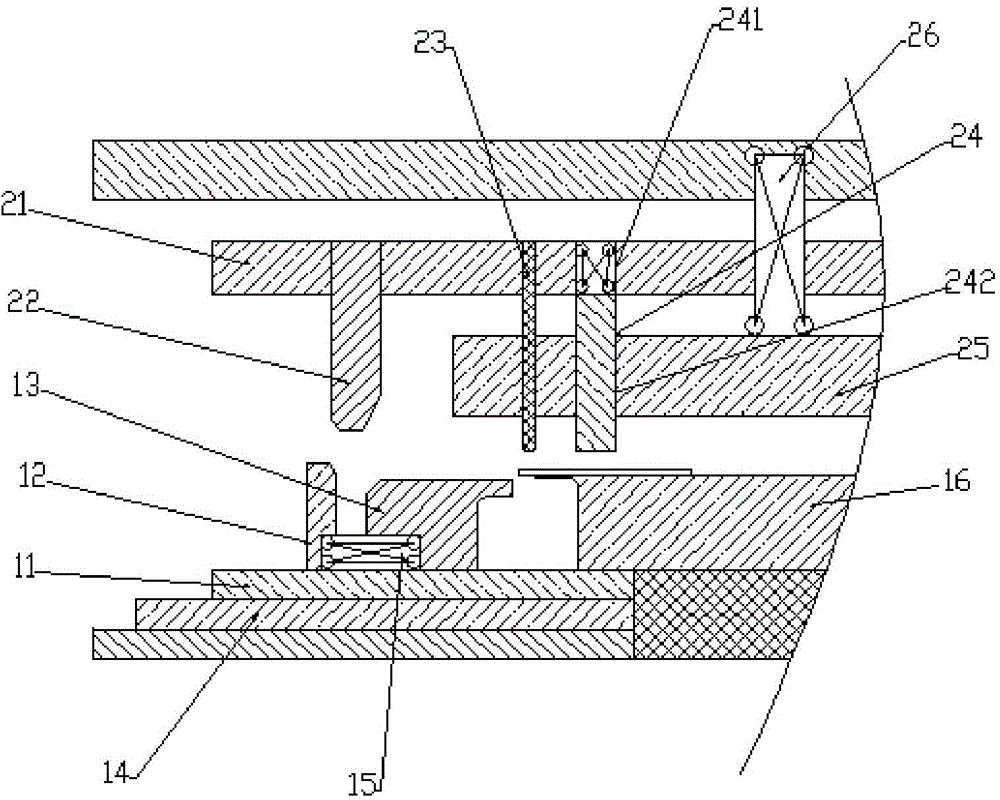
[0021] see figure 1 , a kind of back plate imprinting mould, comprises upper mold assembly and lower mold assembly, and upper mold assembly is positioned at the top of lower mold assembly, and the bottom of lower mold assembly is provided with base; Lower mold assembly includes forming male mold 16 , the lower slider 11, the lower backing plate 14, the lower slider 11 is located on the lower backing plate 14, the upper side of the lower slider 11 is provided with a side pushing forming punch 13 and a lower mold push block 12, the right side of the lower slider 11 A male mold pad is provided, and the forming male mold 16 is arranged on the male mold pad, and the upper end of the forming male mold 16 extends to the left to form an auxiliary male mold. A first reset device 15 is clamped between the push block 12 and the side push forming punch 13; the upper mold assemb...


PUM


Abstract

The invention discloses a back plate engraving die. The back plate engraving die comprises an upper die assembly and a lower die assembly. A base is arranged below the lower die assembly. The lower die assembly comprises a forming male die, a lower sliding block and a lower sliding cushion plate. The lower sliding block is arranged on the lower sliding cushion plate, and a lateral pushing forming punch and a lower die push block are arranged on the lower sliding block. A male die cushion block is arranged on the right side of the lower sliding block. The forming male die is arranged on the male die cushion block. The upper end of the forming male die extends leftwards to form an auxiliary male die, and the lower end face of the auxiliary male die is higher than the upper end face of the lateral pushing forming punch. The upper die assembly comprises an upper die base, an upper die slotting tool, an upper die positive punch, an upper die plate and an engraving punch, wherein the upper die slotting tool is arranged at the bottom of the upper die base, and the upper die positive punch and the engraving punch are fixed to the bottom of the upper die base and penetrate through the upper die plate; the upper die positive punch is located on the left side of the engraving punch. According to the back plate engraving die, engraving and two times of bending can be finished through one procedure, and efficiency is improved; the size of a bent product is accurate, and the product bending quality is guaranteed.

Description

technical field [0001] The invention relates to a mold, in particular to a back plate marking mold. Background technique [0002] Mold, various molds and tools used in industrial production for injection molding, blow molding, extrusion, die-casting or forging forming, smelting, stamping, stretching and other methods to obtain the required products. In short, a mold is a tool used to shape an object. This tool is composed of various parts, and different molds are composed of different parts. It mainly realizes the processing of the shape of the article through the change of the physical state of the formed material. The bending machine is a kind of equipment used for bending sheet materials. The bending principle is to place the workpiece on the plane of the lower die. When the upper die presses the lower die, the workpiece forms a bending angle under the action of the upper and lower dies. [0003] In the mold processing industry, there are often some products that need t...

Claims


Application Information

Patent Timeline
Patent Type & Authority Applications(China)
IPC IPC(8): B21D37/10B21D35/00
CPCB21D37/10B21D35/003
Inventor 李国新
Owner 昆山电子羽电业制品有限公司
Learn More