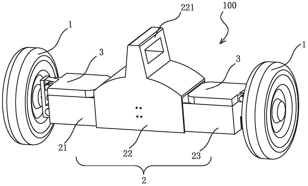
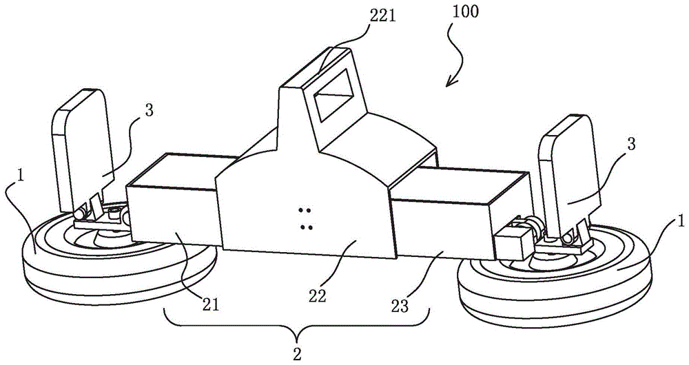
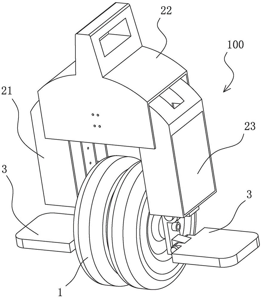
Transformable self-balancing two-wheeled electric vehicle
An electric two-wheel, self-balancing technology, applied to foldable bicycles, motor vehicles, bicycles, etc., can solve problems such as accidents, difficult control of turning, and difficult balance
- Summary
- Abstract
- Description
- Claims
- Application Information
AI Technical Summary
Problems solved by technology
Method used
Image
Examples
Embodiment 1
[0088] Figure 6 A schematic structural diagram of a rotation positioning mechanism 30 according to an embodiment of the present invention is shown. Such as Figure 6 As shown, a rotary positioning mechanism 30 is respectively provided on the left and right sides of the electric two-wheeled vehicle body, and the rotary positioning mechanism 30 is provided with a rotary connector 1 302, a rotating shaft 304, a rotary connector 2 303 and a stepping motor 305, mainly It is used to switch between the unfolded and folded states of the car body, and the second rotating connector 303 is also used to install the left casings 21 and 23 . One end of the first rotating connector 302 is rotatably connected to the pedal 8 , and the other end is connected to one end of the second rotating connector 303 through the rotating shaft 304 . The other end of the second rotating connector 303 is connected to the steering mechanism through another rotating shaft 304 . Stepping motor 305 is arrang...
Embodiment 2
[0092] Figure 7 and 8 A schematic structural diagram of a rotation positioning mechanism 31 according to another embodiment of the present invention is shown. Such as Figure 7-8 As shown, the rotation positioning mechanism 31 is provided with a rotation connector 1 312, a rotation shaft assembly 314 and a rotation connector 2 313, which are mainly used to switch between the unfolded and folded states of the vehicle body. The left casing 21 and the right casing 23 are provided with the second rotating connector 313 . One end of the first rotating link 312 is rotatably connected to the pedal 8 , and the other end of the first rotating link 312 is connected to the second rotating link 313 through the rotating shaft assembly 314 . The other end of the second rotating connector 313 is connected to the steering mechanism through another rotating shaft assembly 314 . The rotary shaft assembly 314 is composed of a bolt 314a, a spring 314c and a nut 314b. When the vehicle body i...
Embodiment 3
[0096] Figure 9 10 and 10 show a schematic structural view of a rotation positioning mechanism 32 according to another embodiment of the present invention. Such as Figure 9-1As shown in 0, the rotary positioning mechanism 32 is provided with a rotary connector 1 322, two sets of ratchet assemblies 324, two rotating shafts 325 and a rotary connector 2 323, which are mainly used to switch the two states of the vehicle body unfolded and folded. The left casing 21 and the right casing 23 are installed on the second rotating connector 322 . One end of the first rotating link 322 is rotatably connected to the pedal, and the other end is rotatably connected to the second rotating link through the ratchet assembly 324 and the rotating shaft 325 . The two sets of ratchet assemblies are respectively fixed on the left casing 21 and the right casing 23 , and are respectively connected to the first rotating connection part and the second rotating connecting part through the rotating sh...
PUM
 Abstract
Description
Claims
Application Information
 - R&D
- Intellectual Property
- Life Sciences
- Materials
- Tech Scout
- Unparalleled Data Quality
- Higher Quality Content
- 60% Fewer Hallucinations
Browse by: Latest US Patents, China's latest patents, Technical Efficacy Thesaurus, Application Domain, Technology Topic, Popular Technical Reports.
© 2025 PatSnap. All rights reserved.Legal|Privacy policy|Modern Slavery Act Transparency Statement|Sitemap|About US| Contact US: help@patsnap.com


