A multifunctional large flow pressure reducing valve for irrigation

A large flow, pressure reducing valve technology, applied in the field of pressure reducing valves, multi-functional large flow pressure reducing valves, can solve the problems that it is difficult to meet the overcurrent requirements of irrigation systems, there is no closing and opening function, and it cannot be used as a valve. Achieve the effect of improving irrigation uniformity, easy maintenance and overhaul, and good pressure regulation effect

Inactive Publication Date: 2017-02-01
CHINA AGRI UNIV
View PDF5 Cites 1 Cited by
  • Summary
  • Abstract
  • Description
  • Claims
  • Application Information

AI Technical Summary

Problems solved by technology

[0006] However, the excess flow of this pressure reducing valve is only 5-15m 3 / h, it is difficult to meet the overcurrent requirements of the branch pipes of the existing irrigation system; the periphery of the flow control chamber 26 of the pressure reducing valve is provided with 4 split columns, and when the water flow enters the flow control chamber 26 through the water intake 28, the split columns will play a role Obstruction effect, increased head loss, higher starting pressure
[0007] And when the above two devices are used in the pipeline irrigation system, they must be used in conjunction with the valve. When the irrigation of a wheel irrigation group is completed, the valve needs to be closed, that is, the above two devices have no closing and opening functions, so they cannot be used as valves.

Method used


Image

  • A multifunctional large flow pressure reducing valve for irrigation
  • A multifunctional large flow pressure reducing valve for irrigation
  • A multifunctional large flow pressure reducing valve for irrigation

Examples


Embodiment Construction

[0033] The preferred implementation method of the present invention will be described in detail below in conjunction with the accompanying drawings.

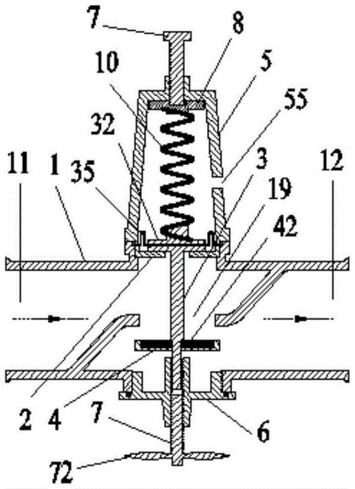
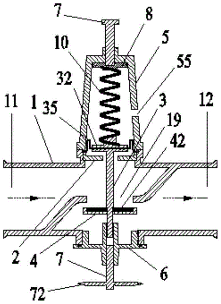
[0034] The present invention adopts the following technical solutions: a multifunctional large flow pressure reducing valve for irrigation, such as figure 1 , figure 2 As shown, the present invention includes a valve body 1 , a support plate 2 , a valve stem 3 , a valve core 4 , a valve cover 5 , a base 6 and an opening and closing valve 7 .

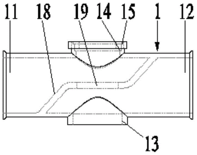
[0035] Such as Figure 3-5 As shown, the valve body 1 is a straight-through cylindrical structure, one end of which is the water inlet end 11, and the other end is the water outlet end 12; the upper and lower parts of the valve body have an opening respectively, and the pipe wall at the lower opening is Extend outward for a certain distance to form a circular opening with the bottom flush, the inner wall of the circular opening is provided with threads, the circular opening end is the ...


PUM


Abstract

The invention relates to a reducing valve in the agriculture water-saving irrigation field and discloses an irrigation multifunctional mass-flow reducing valve. The irrigation multifunctional mass-flow reducing valve comprises a valve body, a support plate, a valve rod, a valve core, a valve cap, a base, an opening-closing valve body, a spring positioning piece, a bolt and a spring. In the working state, when the upstream pressure is instable, under the actions of spring force and water pressure, the valve rod and the valve core can move up and down in the axial direction to regulate the current cross section, then different head losses of localities are caused, and the function of stabilizing the downstream pressure is achieved. According to the irrigation multifunctional mass-flow reducing valve, a throttling port is perpendicular to the water flowing direction, and the pass flow is large; the lowest end of the valve body is provided with the opening-closing valve body, through the adjustment of the opening-closing valve body, the valve core can be closely attached to the wall face of the lower side of the throttling port, and the function of closing the valve is achieved. The irrigation multifunctional mass-flow reducing valve has the advantages that the pass flow is large, the adjusting range is wide, the pressure adjusting effect is good, the assembly is convenient, and the irrigation uniformity can be greatly improved if the irrigation multifunctional mass-flow reducing valve is applied to the agriculture irrigation system; meanwhile, the delicate design of the opening-closing valve body can omit an opening-closing valve body in a pipeline, and the investment is reduced.

Description

technical field [0001] The invention relates to a pressure reducing valve, in particular to a multifunctional large flow pressure reducing valve suitable for branch pipes of pipeline irrigation systems, belonging to the field of agricultural water-saving irrigation. Background technique [0002] In agricultural irrigation, irrigation uniformity is an important index to measure irrigation quality. However, due to differences in terrain and the distance between the head and the downstream irrigation plots, the water pressure at the entrance of each irrigation plot will change, resulting in irrigation uniformity that does not meet the specification requirements. In order to effectively control the irrigation uniformity of the entire irrigation system, it is a better solution to install pressure regulating equipment at the inlet branch pipes of each irrigation area, which can ensure that the inlet pressure of each irrigation area is the same. [0003] Introduce the many deficie...

Claims


Application Information

Patent Timeline
Patent Type & Authority Patents(China)
IPC IPC(8): F16K17/30F16K41/12F16K1/46
CPCF16K1/46F16K17/30F16K41/12
Inventor 李光永柴海东莫彦
Owner CHINA AGRI UNIV
Why Eureka
Try Eureka