
Pulverized coal accumulation prevention fixing shrinkage cavity device with horizontally-arranged primary air pipes for boiler coal pulverizing system

A pulverizing system and fixed shrinkage cavity technology, which is applied in the direction of combustion air/fuel supply, block/powder supply/distribution, combustion method, etc. It can solve delay, large average deviation of air volume distribution between pipelines, complex adjustment, etc. problem, achieve the effect of uniform speed and avoid the risk of smoldering explosion

Inactive Publication Date: 2015-08-26
STATE GRID CORP OF CHINA +1
View PDF5 Cites 0 Cited by
  • Summary
  • Abstract
  • Description
  • Claims
  • Application Information

AI Technical Summary

Problems solved by technology

If the primary wind speed is too high, the ignition will be delayed, and if it is too low, the burner will be burned easily, and coal dust will be deposited in the primary air duct
Too high or too low secondary wind speed may disrupt the normal mixing disturbance of the airflow
The adjustable shrinkage cavity is flexible to use, and can be adjusted in cold and hot states according to needs, but the adjustment is complicated
The structure of the fixed shrinkage cavity is simple and does not need to be adjusted after installation, but the system needs to be accurately calculated. When the wear of the shrinkage cavity is serious and the average deviation of the air volume distribution between the pipes is large, which seriously affects the combustion conditions in the furnace and the thermal efficiency of the boiler, the shrinkage cavity needs to be replaced. plate
[0005] For a 1000MW unit burning bituminous coal boilers, there are 48 burners, and there are more burners for lignite boilers. If an adjustable shrinkage cavity is installed, the adjustment workload is very large

Method used


Image

  • Pulverized coal accumulation prevention fixing shrinkage cavity device with horizontally-arranged primary air pipes for boiler coal pulverizing system
  • Pulverized coal accumulation prevention fixing shrinkage cavity device with horizontally-arranged primary air pipes for boiler coal pulverizing system

Examples


specific Embodiment approach

[0023] detailed description: Below in conjunction with accompanying drawing, the present invention will be further described:

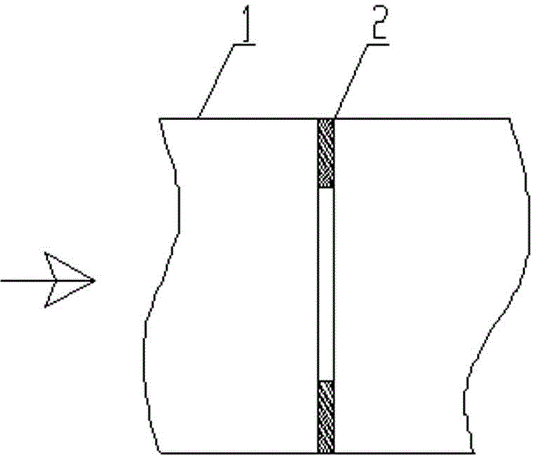
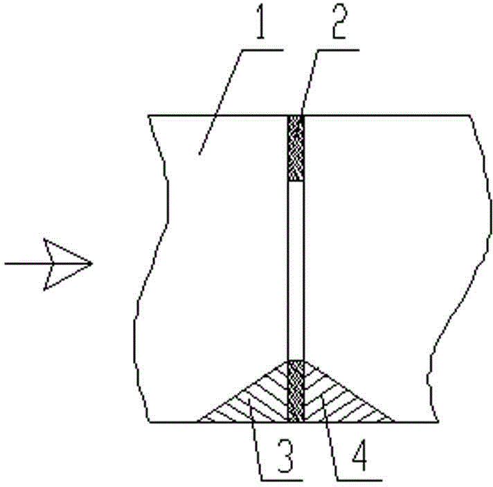
[0024] Such as figure 1 As shown, the present invention provides a non-powder-accumulating fixed shrinkage cavity device with a horizontally arranged primary air duct of a boiler pulverizing system. The device includes a horizontally installed primary pulverized coal air duct 1 and a fixed The shrinkage cavity 2 is provided with slope-shaped anti-powder accumulation devices 3 on both sides of the lower end of the fixed shrinkage cavity 2 that gradually slope downward to both sides. The unique anti-powder accumulation device 3 on the slope realizes the purpose of avoiding powder accumulation.


PUM


Abstract

The invention discloses a pulverized coal accumulation prevention fixing shrinkage cavity device with horizontally-arranged primary air pipes for a boiler coal pulverizing system. The device comprises the horizontally-installed primary pulverized coal air pipes and fixing shrinkage cavities formed in the primary pulverized coal air pipes. The two sides of the lower end of each fixing shrinkage cavity are provided with slope-shaped pulverized coal accumulation prevention devices inclined downwards gradually to the two sides. The horizontally-installed pulverized coal accumulation prevention fixing shrinkage cavity device has the advantages that pulverized coal accumulation is prevented, and when existing, the pulverized coal will slip off along the slopes to be prevented from accumulating; the device has a throttling effect, and the speeds of the primary air pipes of a same-layer burner can be controlled to be uniform; after the pulverized coal accumulation prevention fixing shrinkage cavity device is horizontally installed, it is unnecessary to conduct a leveling test on the primary air pipes; the risk that pulverized coal accumulates on the upper portions of the horizontally-formed fixing shrinkage cavities and smolders to explode can be avoided; the horizontally-installed pulverized coal accumulation prevention fixing shrinkage cavity device has wear resistance.

Description

technical field [0001] The invention relates to a non-powder-accumulating fixed shrinkage cavity device arranged horizontally in a primary air pipe of a boiler pulverizing system, which is applied to the pulverized coal boiler pulverizing system of a thermal power plant. Background technique [0002] It is one of the basic conditions necessary for the establishment of a normal aerodynamic field and stable combustion for the burner to maintain an appropriate uniform velocity at the outlet of the primary air, secondary air and separated exhaust air (OFA air or SOFA air). If the primary wind speed is too high, the ignition will be delayed, and if it is too low, the burner will be burned easily, and coal dust will be deposited in the primary air duct. Too high or too low secondary wind speed may destroy the normal mixing disturbance of the airflow. Thereby reducing the stability and economy of combustion. Separated overfire air is a staged combustion air to control nitrogen ox...

Claims


Application Information

Patent Timeline
Patent Type & Authority Applications(China)
IPC IPC(8): F23L1/00F23K3/02
Inventor 冷杰冷柏炟史耕金邹天舒吴景兴丛日成商华张建志张幼明
Owner STATE GRID CORP OF CHINA
Learn More