Water turbine type splashing device

A technology of splash device and water turbine, which is applied in the direction of water shower coolers, direct contact heat exchangers, lighting and heating equipment, etc. Splash impeller speed and other issues, to avoid a large drop in hydraulic power, improve the effect of water distribution, and improve the effect of cooling

Inactive Publication Date: 2015-08-26
广东粤电中山热电厂有限公司 +1
View PDF8 Cites 4 Cited by
  • Summary
  • Abstract
  • Description
  • Claims
  • Application Information

AI Technical Summary

Problems solved by technology

The disadvantages of the existing technology are: ①. After the cooling water flows through the volute, hydraulic loss will occur, resulting in a slow speed of the splash impeller, uneven water distribution, and affecting the heat dissipation effect of the cooling tower; ②. The volute of the existing structure The structure of the water outlet makes the hydraulic power of the water outlet drop seriously, which further affects the speed of the splash impeller; ③. The bracket will hinder the splashing of the cooling water, which will further affect the uniformity of the cooling water splash distribution, thereby further affecting the heat dissipation of the cooling tower Effect; ④, limited by the pipeline layout of the sprinkler system, there are many branch pipes and elbows in the sprinkler system, resulting in a large hydraulic loss, uneven water distribution, and poor heat dissipation

Method used


Image

  • Water turbine type splashing device
  • Water turbine type splashing device
  • Water turbine type splashing device

Examples


Embodiment 1

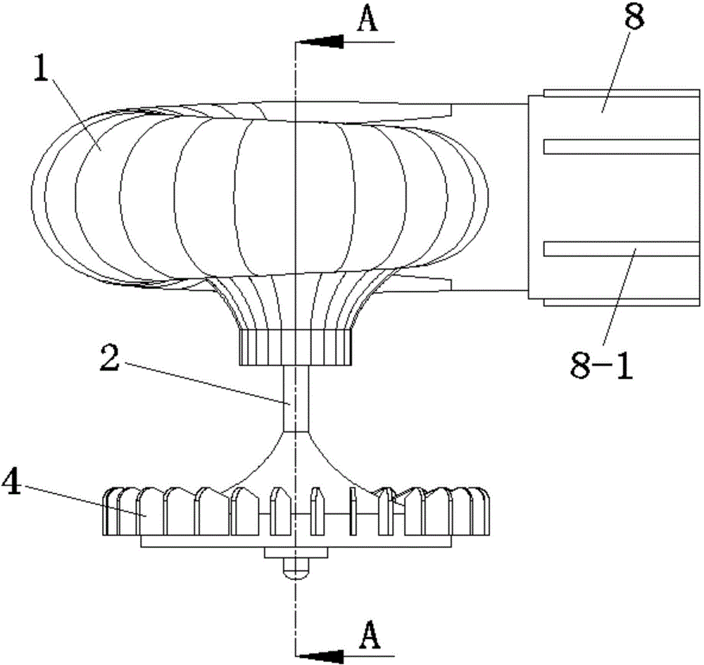
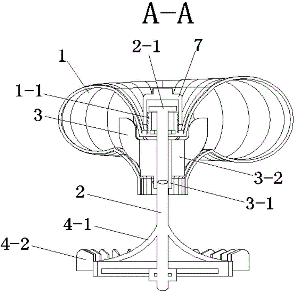
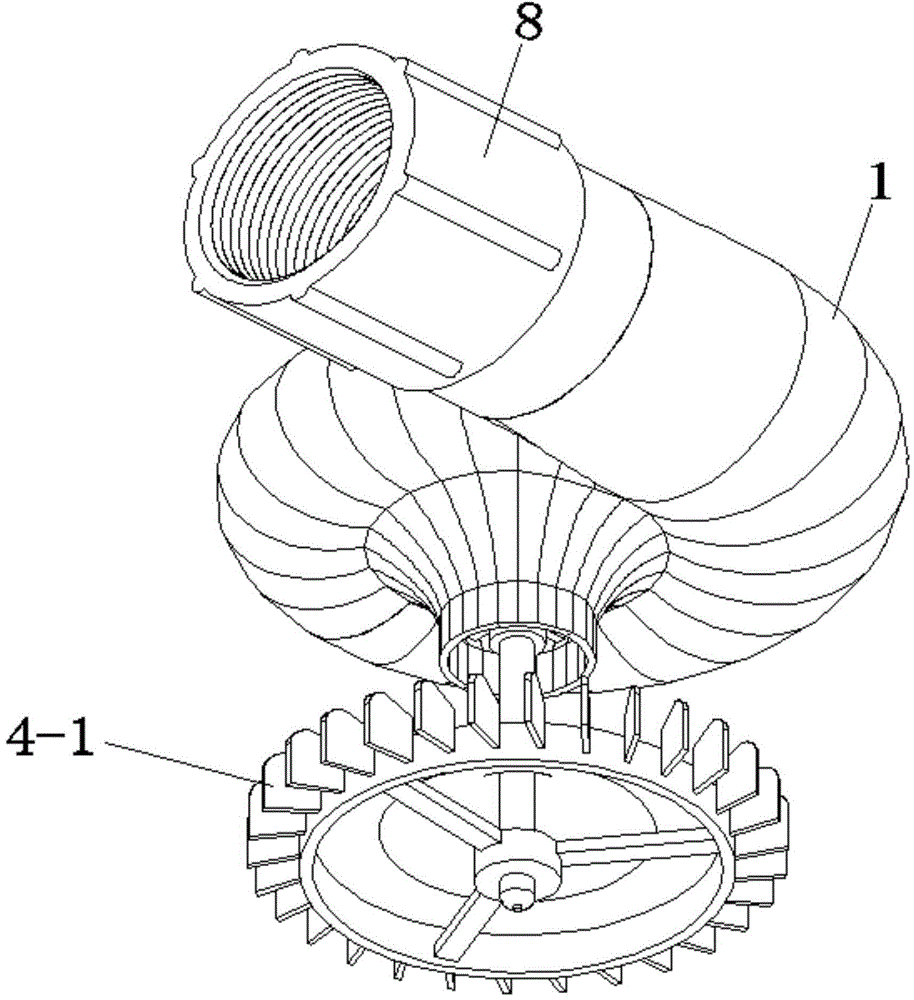
[0044] See Figure 1 to Figure 4 , the water turbine type splash device of the present embodiment can be made of any material, including volute 1, main shaft 2, hydrocyclone impeller 3, split splash impeller 4, bearing 5, rubber washer 6, pipe cap 7, connecting nut 8 and flow controller9.

[0045] The side and the bottom of the volute 1 are respectively provided with a water inlet and a water outlet. The flow controller 9 is installed at the water inlet of the volute 1 through the connecting nut 8 . A reinforcing rib 8-1 is provided on the outer periphery of the connecting nut 8. The flow controller 9 is a conical pipe. The flow channel in the volute 1 is in the shape of an equiangular spiral with a wrap angle of 360°, and the center of the volute 1 is a funnel-shaped structure with upper and lower layers. The upper part of the main shaft 2 runs through the two-layer funnel-shaped structure of the volute 1, and a circular baffle 2-1 is arranged on the top thereof. The bea...

Embodiment 2

[0051] This embodiment is basically the same as Embodiment 1, except that the flow controller 9 is installed at the water outlet of the volute 1 through a connecting nut 8 .


PUM


Abstract

The invention discloses a water turbine type splashing device. The water turbine type splashing device comprises a volute, a main shaft, a water rotating impeller and a splashing impeller. The side portion and the bottom of the volute are provided with a water inlet and a water outlet respectively. The upper portion of the main shaft is arranged in the water outlet of the volute and connected with the volute in a rotating mode. The water rotating impeller is fixed to the upper portion of the main shaft and located in the water outlet of the volute. The center of the splashing impeller is fixed to the lower portion of the main shaft and located below the water outlet of the volute. The water rotating impeller fixed to the main shaft is arranged in the volute, through two-stage rotation drive, the rotating speed of the splashing impeller is guaranteed, the grain size of water drops is smaller, the water distributing effect is effectively improved, and therefore the cooling effect of a cooling tower is effectively improved.

Description

technical field [0001] The invention relates to a water turbine type splashing device. Background technique [0002] Splashing devices for cooling towers mainly include reflective and centrifugal types, among which centrifugal splashing is a newly emerging splashing technology. The existing centrifugal splash device mainly includes a volute and a splash impeller, the water supply pipe is connected with the volute, and the splash impeller is installed under the water outlet of the volute through a bracket. The water supply pipe supplies cooling water, which generates rotational power after passing through the volute, and finally sprays the cooling water through the rotation of the splash impeller. The disadvantages of the existing technology are: ①. After the cooling water flows through the volute, hydraulic loss will occur, resulting in a slow speed of the splash impeller, uneven water distribution, and affecting the heat dissipation effect of the cooling tower; ②. The volu...

Claims


Application Information

Patent Timeline
Patent Type & Authority Applications(China)
IPC IPC(8): F28F25/06
Inventor 刘剑卿郑源陈倩王建波盛立君周斌费志华
Owner 广东粤电中山热电厂有限公司
Why Eureka
Try Eureka