
Self-catapulting launching device for guided missile

A technology for launching devices and missiles, applied in the direction of launching devices, etc., can solve the problems of serious impact and ablation of the ship deck, unable to achieve modular installation, endangering the safety of ships and personnel, and achieve good thermal protection effect. , to ensure the emission efficiency and reliability, reduce the effect of impact and ablation

Inactive Publication Date: 2015-08-26
BEIJING INSTITUTE OF TECHNOLOGYGY
View PDF3 Cites 17 Cited by
  • Summary
  • Abstract
  • Description
  • Claims
  • Application Information

AI Technical Summary

Problems solved by technology

[0009] 1) The impact and ablation effect of the engine plume flow field on the ship deck is serious after the missile is ejected;
[0010] 2) If the missile fails to ignite, it is likely to explode, endangering the safety of ships and personnel
[0016] 1) The launching device has a complex structure and a large mass, making modular installation impossible;
[0017] 2) The missile is overloaded;
[0020] 5) The refilling process is complex and time-consuming

Method used


Image

  • Self-catapulting launching device for guided missile
  • Self-catapulting launching device for guided missile
  • Self-catapulting launching device for guided missile

Examples


Embodiment Construction

[0039] The present invention will be described in detail below with reference to the accompanying drawings and examples.

[0040] The principle of the self-ejection launch device is to convert the high-energy gas flow field ejected by the missile engine into the ejection power of the missile in the limited space formed by the bottom of the barrel and the adapter.

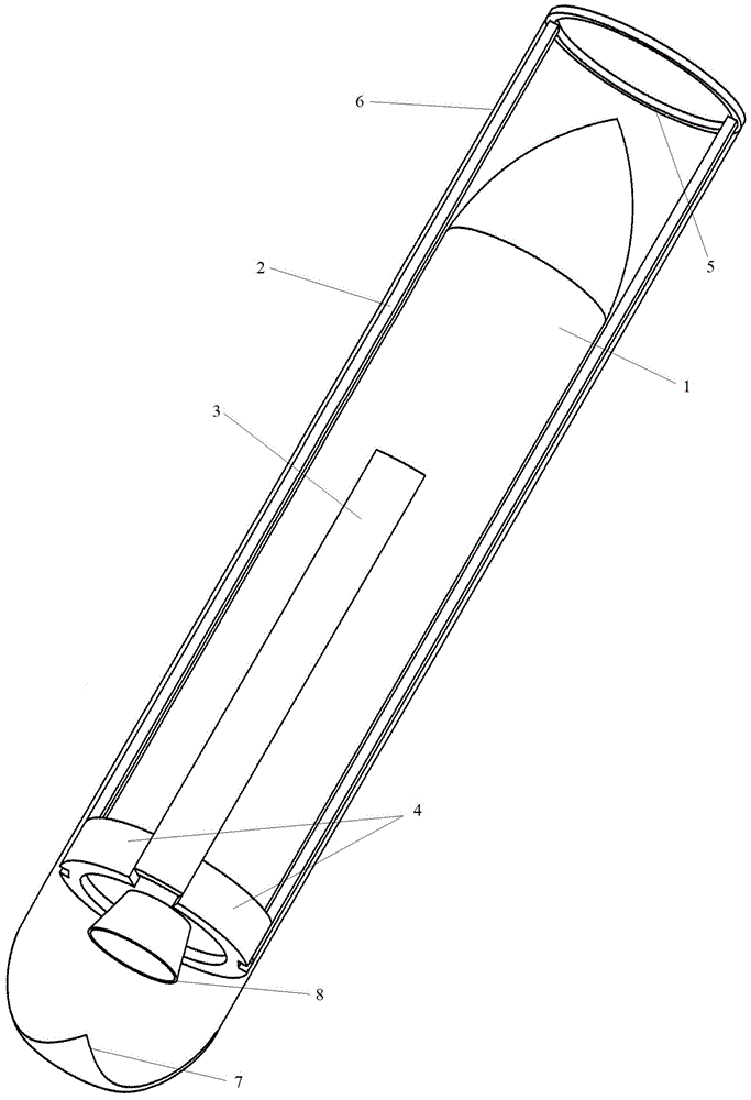
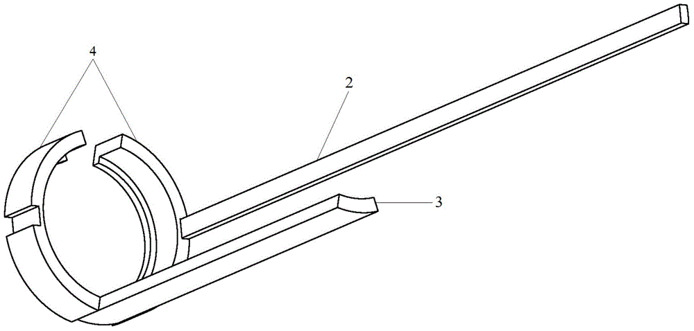
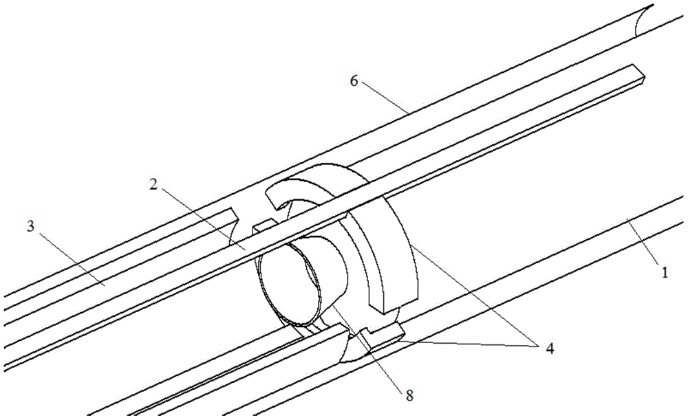
[0041] The invention provides a missile self-ejection launching device, comprising a guide cone (7), a limit mechanism, a buffer device (5), two long guide rails (2), two short guide rails (3) and two adapters ( 4);

[0042] The diversion cone (7) is a metal cone or a cone-like.

[0043] Buffer device (5) is a metal ring.

[0044] The stop mechanism is a metal ring that holds the adapter.

[0045] The length of the short guide rail (3) is between 1 / 3 and 2 / 3 of the length of the long guide rail (2).

[0046] The adapter (4) is a ring structure, and a groove is arranged in the middle of the outer edge of the ring...


PUM


Abstract

The invention provides a self-catapulting launching device for a guided missile. The self-catapulting launching device comprises a flow-guiding cone, a limiting mechanism, a buffering device, a long guide rail, a short guide rail and adaptors; the flow-guiding cone is fixedly connected to the bottom end of a launching cylinder, the buffering device is fixedly connected to the outlet of the launching cylinder, the long guide rail and the short guide rail are fixed to the inner wall of the launching cylinder in the axis direction of the launching cylinder and are staggered and evenly distributed in the launching cylinder, grooves of the adaptors are slidingly matched with the long guide rail, gaps between two adjacent adaptors are slidingly matched with the short guide rail, the limiting mechanism is fixedly connected to the inner wall of the launching cylinder, the adaptors are limited to move to the interior of the cylinder in the axis direction of the launching cylinder, and after guided missile is filled, a closed space is defined by the bottoms of the adaptors, the bottom of the guided missile, the end face of the bottom of the long guide rail and the end face of the bottom of the short guide rail in the launching cylinder. The initial launching precision of the guided missile can be improved, and the manufacturing cost and the maintenance cost of the launching device are effectively lowered.

Description

technical field [0001] The invention belongs to the technical field of missile launching devices, and in particular relates to a missile self-catapulting launching device. Background technique [0002] At present, there are two commonly used missile launch technologies in the world. One is thermal launch, that is, the missile is launched directly from the launch tube by using the thrust of the main engine; Speed ​​and then the firing mode of the engine ignition. In the early ship-borne missile launch systems, the United States and other Western countries mostly used thermal launch technology, such as the MK41 vertical launch system in the United States; while Russia focused on ejection technology, such as the SA-N-6 vertical launch system. At the beginning of the 1990s, the United States demonstrated and compared the two launch technologies, and gradually began to pay attention to ejection technology. Western countries began to develop vertical ejection systems suitable for...

Claims


Application Information

Patent Timeline
Patent Type & Authority Applications(China)
IPC IPC(8): F41F7/00
Inventor 姜毅董晓彤于邵祯
Owner BEIJING INSTITUTE OF TECHNOLOGYGY
Learn More