
Strength and rigidity testing fixture for aircraft draw bar and use method of strength and rigidity testing fixture

A technology of aircraft traction and test fixtures, which is applied in the field of stiffness test loading and aircraft structural strength, and can solve problems such as high cost, low cost, and high risk

Active Publication Date: 2015-08-26
SHENYANG AIRCRAFT CORP
View PDF8 Cites 12 Cited by
  • Summary
  • Abstract
  • Description
  • Claims
  • Application Information

AI Technical Summary

Problems solved by technology

[0002] At present, there are two test methods for the structural strength and stiffness tests of aircraft parts. One is to test directly on the fuselage. The test requires an aircraft. The data obtained from the test is accurate and reliable, but due to the high cost, it is dangerous The reliability is also relatively large, and this method is generally not used now; the other is to design a test fixture, and install the tested parts on the test fixture to simulate its stress state for testing. This test method has low cost and low risk. Therefore, any test using the second group of methods must be designed and calculated based on relevant data, which is a process from scratch, and each test fixture must ensure the test state of the test piece The similarity with the state of use is maximized, the test fixture must have sufficient strength and rigidity, and no error will be caused to the test results due to the deformation or destruction of the fixture, and the fixture must have good processing technology and installation technology

Method used


Image

  • Strength and rigidity testing fixture for aircraft draw bar and use method of strength and rigidity testing fixture
  • Strength and rigidity testing fixture for aircraft draw bar and use method of strength and rigidity testing fixture

Examples


Embodiment Construction

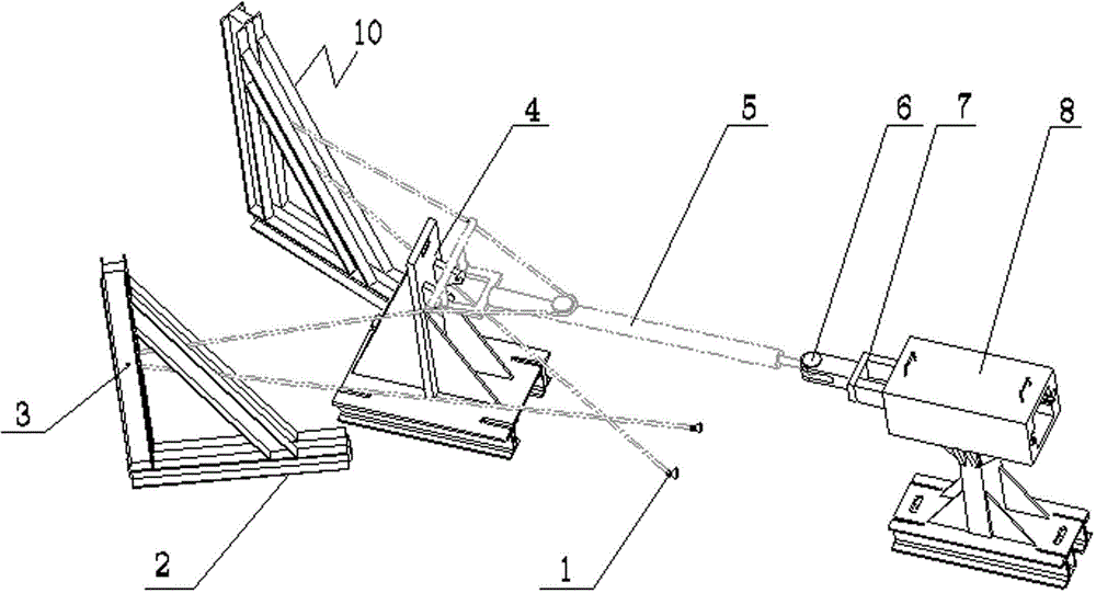
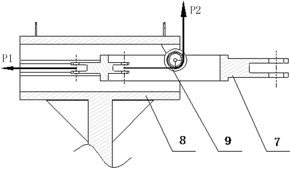
[0017] Such as figure 1 with figure 2 As shown, a kind of aircraft drawbar strength, rigidity test fixture, the front end traction ring of test piece 5 is connected with one end of main loading mechanism 7 through connecting pin 6, and main loading mechanism 7 can pass through its own bearing and slideway mechanism 8 guide rails. Sliding freely in the slideway mechanism 8, a fixed pulley I9 is ​​set at the end of the cavity of the slideway mechanism 8, and the other end of the main loading mechanism 7 located in the slideway mechanism 8 is provided with loading joints in two directions to connect two Steel wire ropes, one is the steel wire rope pulled to the outside P1, and the other is inwardly bypassing the fixed pulley I9 and passing through the inner end of the slideway mechanism 8 along the direction of P2 force; The landing gear fixture 10, the rear end joint of the test piece is connected with the simulated front landing gear fixture 4, and the steel wire rope of the ...


PUM


Abstract

The invention relates to a strength and rigidity testing fixture for an aircraft draw bar. A front-end towing ring of a test piece is connected with one end of a main loading mechanism through a connecting pin, the main loading mechanism can slide freely in a guide rail of a slideway mechanism through a bearing per se, a fixed pulley I is arranged at the end part of the cavity of the slideway mechanism, two loading connectors in two directions are arranged at the other end of the main loading mechanism in the slideway mechanism and respectively connected two steel wire ropes, a rear-end connector of the test piece is connected with a simulative front undercarriage fixture, the steel wire ropes of the test piece bypass fixed pulleys II of load-bearing upright posts to be connected with a simulative main undercarriage fixture, and connectors adopting lug sheet forms at the tail end of the steel cable ropes can be directly connected with conventional fasteners. The testing fixture realize that the connecting mode and the strained condition of the test piece are consistent with the use state, the compression loading does not generate a lateral component force under the high-loaded condition, the occupied space is small, and the manufacturing cost is low. The test method is safe and reliable, the measured data are true and effective and the test efficiency is greatly improved.

Description

technical field [0001] The invention relates to a strength and stiffness test fixture of an aircraft drawbar and a use method thereof, which are used in the loading technology of the strength and stiffness tests of the aircraft structure. Background technique [0002] At present, there are two test methods for the structural strength and stiffness tests of aircraft parts. One is to test directly on the fuselage. The test requires an aircraft. The data obtained from the test is accurate and reliable, but due to the high cost, it is dangerous The reliability is also relatively large, and this method is generally not used now; the other is to design a test fixture, and install the tested parts on the test fixture to simulate its stress state for testing. This test method has low cost and low risk. Therefore, any test using the second group of methods must be designed and calculated based on relevant data, which is a process from scratch, and each test fixture must ensure the te...

Claims


Application Information

Patent Timeline
IPC IPC(8): G01N3/04
Inventor 王明月
Owner SHENYANG AIRCRAFT CORP
Learn More