Tool for preventing carbon brush from direction error in installation

A technology of installation direction and carbon brush, applied in the direction of electromechanical devices, manufacturing motor generators, electrical components, etc., can solve the problems of poor contact between carbon brushes and slip rings, ineffective and timely detection, unreliability, etc., to save manual inspection and direction testing process, avoid rework and material cost, control the effect of outflow of defective products

Active Publication Date: 2015-08-26
JIANGSU YUNYI ELECTRIC
View PDF7 Cites 0 Cited by
  • Summary
  • Abstract
  • Description
  • Claims
  • Application Information

AI Technical Summary

Problems solved by technology

The shape of the carbon brush is mostly inclined and has a direction. If the direction of the regulator carbon brush is reversed, it will cause poor contact between the carbon brush and the slip ring, and the faster wear of the carbon brush will shorten the life of the regulator, or produce strong noise and other adverse consequences.
[0003] The existing carbon brush installation methods for automotive generator regulators are all purely mechanical structures. There are springs behind the carbon brushes of the regulator to withstand the carbon brushes. When the carbon brushes are assembled, the springs are in a compressed state and are only used to fix the product and control. The protruding length of the carbon brush and the wrong assembly direction of the carbon brush cannot be found effectively and in time. At present, the method of controlling the direction of the carbon brush is mainly to rely on the visual inspection of personnel
This installation method has always had the following problems: (1) When the carbon brush is assembled in the wrong direction, it cannot be found effectively and in time
[0004] (2) After assembly, it is necessary to re-inspect and increase the process, wasting man-hours
[0005] (3) The efficiency of personnel visual inspection is low and unreliable, and it is easy to miss inspection due to personnel negligence, so that defective products flow out

Method used


Image

  • Tool for preventing carbon brush from direction error in installation
  • Tool for preventing carbon brush from direction error in installation
  • Tool for preventing carbon brush from direction error in installation

Examples


Embodiment Construction

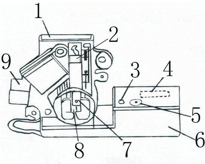
[0025] Such as figure 1 , figure 2 , image 3 , Figure 4 , Figure 5 and Figure 6 Shown: the present invention comprises regulator 9, carbon brush length control block 1, PCB trigger plate 8, alarm device 6, carbon brush 2 is housed on regulator 9, and carbon brush length control block 1 is also housed on regulator 9 , the PCB trigger board is installed on the carbon brush length control block 1, and the right end of the regulator 9 is provided with an alarm device 6, and the alarm device 6 has a built-in light-emitting diode 3, a piezoelectric active buzzer 5, a battery 4.

[0026] The battery is 9V. The light-emitting diode is 5V, and the piezoelectric active buzzer is 3-15V.

[0027] The PCB trigger board 8 is connected to the light-emitting diode 3 and the piezoelectric active buzzer 5 through wires. When the direction of the regulator carbon brush 2 is reversed, the high head of the carbon brush is pressed on the PCB trigger board 8, so that the positive trigger...


PUM


Abstract

The invention discloses a tool for preventing a carbon brush from direction error in installation. The tool comprises a regulator, a carbon brush length control block, a PCB trigger plate and an alarm device; and the carbon brush is mounted on the regulator. The tool is characterized in that the carbon brush length control block is mounted on the regulator, the PCB trigger plate is mounted on the carbon brush length control block, the alarm device is arranged at the right end of the regulator and internally provided with an LED, a piezoelectric active buzzer and a battery, and the PCB trigger plate is connected with the LED and the piezoelectric active buzzer via leads. The tool has the advantages that the alarm device is triggered no matter which position of the PCB trigger plate is pressed when the carbon brush is mounted reversely, pseudo-connection does not occur, and during use, the tool is sensitive for triggering, safe and reliable.

Description

technical field [0001] The invention relates to an automobile generator regulator, which is used to prevent mistakes in the direction of carbon brushes during the assembly process of directional carbon brushes or to detect the directions of carbon brushes in finished regulators, in particular to a jig for preventing mistakes in the installation direction of carbon brushes. . Background technique [0002] The automotive generator regulator contacts and energizes the slip ring of the generator rotor through the carbon brush, so as to realize the detection and adjustment of the voltage, current and speed of the generator. The shape of the carbon brush is mostly inclined and has a direction. If the direction of the carbon brush of the regulator is reversed, it will cause poor contact between the carbon brush and the slip ring, and the faster wear of the carbon brush will shorten the life of the regulator, or produce strong noise and other adverse consequences. [0003] The exis...

Claims


Application Information

Patent Timeline
Patent Type & Authority Applications(China)
IPC IPC(8): H02K15/00
Inventor 姚猛
Owner JIANGSU YUNYI ELECTRIC
Why Eureka
Try Eureka