Antenna

An antenna and central axis technology, applied in resonant antenna, antenna grounding device, mid-position feed between antenna terminals, etc., can solve the problem of low cut-off frequency, etc., and achieve the effect of expanding the use frequency band

Active Publication Date: 2015-08-26
株式会社诺伊兹研究所 +1
View PDF4 Cites 0 Cited by
  • Summary
  • Abstract
  • Description
  • Claims
  • Application Information

AI Technical Summary

Problems solved by technology

However, in the antenna 100 disclosed in Japanese Unexamined Patent Application Publication No. 2012-195713, the lower limit cutoff frequency cannot be lowered to a lower frequency band (for example, 700 MHz) while maintaining its miniaturization while maintaining a wide frequency band. Cannot make VSWR below 2 in all frequency bands

Method used


Image

  • Antenna
  • Antenna
  • Antenna

Examples


Embodiment Construction

[0090] In order to make the above-mentioned and other purposes of the present invention, the features and advantages more obvious and understandable, the preferred embodiments of the present invention are specifically cited below, and are described in detail as follows:

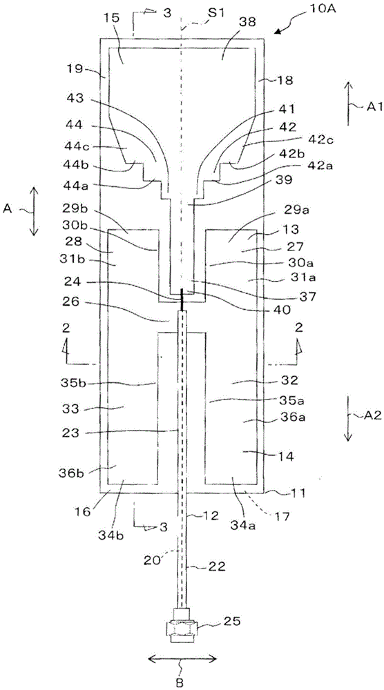
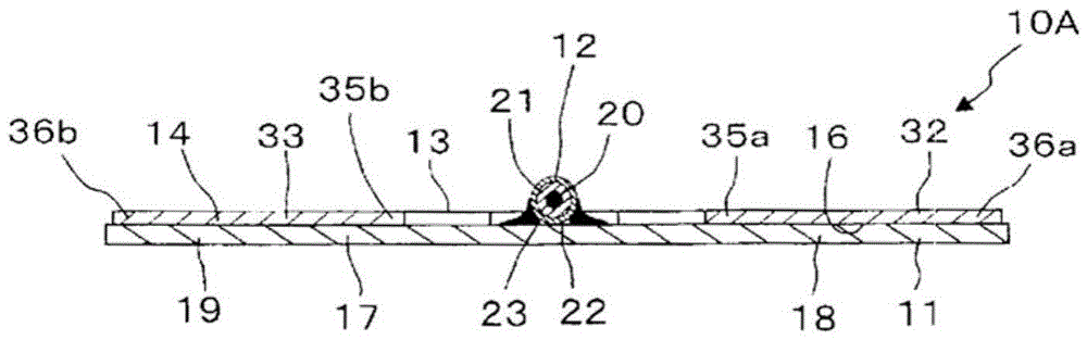
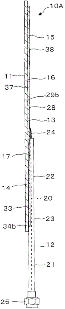
[0091] Referring to the top view of the antenna 10A disclosed as an example figure 1 When an embodiment of the antenna of the present invention is described in detail with reference to the attached drawings, it will be as follows. Furthermore, figure 2 yes figure 1 The sectional view viewed by the 2-2 line arrow, image 3 yes figure 1 The sectional view viewed by the 3-3 line arrow. figure 1 Here, the axial direction is indicated by arrow A, the width direction is indicated by arrow B, the axial front is indicated by arrow A1, and the axial rear is indicated by arrow A2. figure 1 In , the central axis S1 is indicated by a dotted line.

[0092] The antenna 10A is composed of a dielectric substrate ...


PUM

PropertyMeasurementUnit
Sizeaaaaaaaaaa

Abstract

[Problem] To provide an antenna that can be used over a broad bandwidth. [Solution] An antenna (10A) is provided with: a dielectric substrate (11); an unbalanced power supply member (12) having a parasitic part (23) and a power supply part (24); a resonance conductor (13) having a connection area (26), a first resonance area (27), and a second resonance area (28); a ground conductor (14) having a first ground area (32) and a second ground area (33); and a radiation conductor (15) having a first radiation area (37) and a second radiation area (38). On the antenna (10A), first through third radiation stepped portions (42a-42c) are formed in a first rear end part (41) of the second radiation area (38), and first through third radiation stepped portions (44a-44c) are formed on a second rear end part (43) of the second radiation area (38).

Description

technical field [0001] The present invention relates to an antenna provided with an unbalanced feeding element, a resonant conductor, a ground conductor, and a radiation conductor. Background technique [0002] existing antenna, Figure 15 The antenna 100 disclosed in Japanese Unexamined Patent Application Publication No. 2012-195713 includes an unbalanced power feed member having an outer conductor and an inner conductor such as a coaxial cable, and a plate-shaped parasitic element formed in an H shape in plan. Such as Figure 15 As shown, the antenna 100 includes an unbalanced power supply element 111 , a resonant conductor 112 , a ground conductor 113 , and a power supply element 114 . The resonant conductor 112 is constituted by first and second resonant conductors 120 a and 120 b parallel to the feeding part 118 and extending axially forward of the unbalanced feeding element 111 . The grounding conductor 113 is composed of a fixed part 125 electrically connected to the...

Claims


Application Information

Patent Timeline
IPC IPC(8): H01Q9/18H01Q1/38H01Q9/28H01Q9/40
CPCH01Q1/38H01Q9/40H01Q1/48
Inventor 久保崇将石田武志宇野亨山崎太郎森下久作间正雄野岛昭彦庆野浩规弓场庆吾
Owner 株式会社诺伊兹研究所
Why Eureka
Try Eureka