Passive mechanical artificial limb mechanism controlled by electromagnet

A technology for electromagnets and prosthetics, which is applied in the fields of prosthesis, medical science, artificial arms, etc., can solve the problems of low practicability, cumbersome power supply, and cumbersome mechanism, and achieve the effect of convenient use, good experience, and cost reduction.

Inactive Publication Date: 2015-09-02
SHANGHAI UNIV
View PDF14 Cites 4 Cited by
  • Summary
  • Abstract
  • Description
  • Claims
  • Application Information

AI Technical Summary

Problems solved by technology

However, most of them are only used for beautiful fixed prostheses, and other hand-assisted fingers that can restore partial hand functions are driven by external forces, such as motor drives and cylinder drives. Prosthetic control system and bulky power supply
Although these prosthetic control systems can control and realize some complex actions relatively speaking, due to the complex design and strict material requirements, the cost is very expensive, the mechanism is bulky, the battery life is low, the force is not large, the waterproof performance is not good, and the reliability is low. and poor applicability
These shortcomings make its practicability not high, and its application is not very extensive.

Method used


Image

  • Passive mechanical artificial limb mechanism controlled by electromagnet
  • Passive mechanical artificial limb mechanism controlled by electromagnet
  • Passive mechanical artificial limb mechanism controlled by electromagnet

Examples


Embodiment Construction

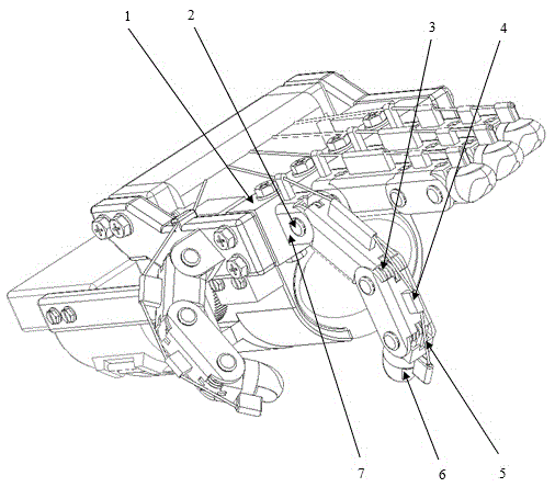
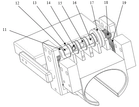
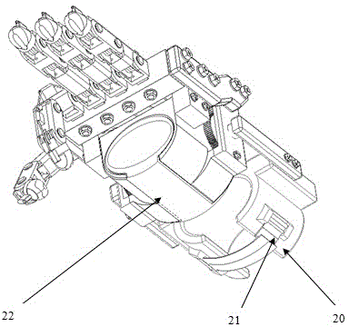
[0014] Such as Figure 1 to Figure 4 As shown, the passive mechanical prosthesis mechanism controlled by the electromagnet of the present invention includes the following three parts:

[0015] One, power mechanism

[0016] The power mechanism is mainly composed of a palm cover 1, a wrist cover 20, a sticky button 21, an inner bushing 22 and a large gear 19. The wrist cover is firmly fixed on the wrist through the sticky button, and the palm cover is fixed on the back of the palm through the inner bushing. . When the wrist rotates, the palm and the wrist rotate. At this time, the palm cover on the palm rotates with the palm relative to the wrist, thereby driving the large gear fixed with the palm cover to rotate, so that the force on the wrist Just pass on the big gear by the relative motion between the palm and the wrist. At this time, the rotation of the large gear drives the meshed small gear to rotate, thereby transmitting the force on the wrist to the front end of the f...


PUM


Abstract

The invention provides a passive mechanical artificial limb mechanism controlled by an electromagnet. The mechanism comprises a power mechanism, a transmission mechanism and an executing mechanism, wherein the power mechanism mainly consists of a palm sleeve, a wrist sleeve, a hoop and fastener, an inner lining sleeve and a bull gear; the wrist sleeve is firmly fixed to a wrist through the hoop and fastener; the palm sleeve is fixedly arranged on the rear part of the palm through the inner lining sleeve; the transmission mechanism mainly consists of a pinion, a wire wheel shaft, a wire wheel, a steel wire rope, an electromagnetic coil and a groove; the wire wheel shaft is provided with a plurality of grooves; an electromagnet, a spring and a key are arranged in each groove; the keys are positioned on the side faces of the springs; the electromagnetic coils sleeve the wire wheel shaft; the wire wheel is connected with the steel wire rope; the bull gear is engaged with the pinion; the pinion is connected with the wire wheel shaft; the wire wheel is connected with the wire wheel shaft through the keys; the executing mechanism consists of finger middle parts, a finger root, a fingertip, a torsion spring shaft and a torsion spring; the finger root and the fingertip are connected through the torsion spring shaft; one torsion is arranged between two finger middle parts. The mechanism has a simple structure and is convenient and practical.

Description

technical field [0001] The invention relates to a passive mechanical prosthetic mechanism controlled by an electromagnet. Through the mechanism and its control method, patients can recover part of hand functions. Background technique [0002] In recent years, with the frequent occurrence of domestic traffic accidents and production accidents, there are more and more hand disabled people. According to a sample survey of disabled people, there are currently about 60 million physically disabled people in my country. Among these disabled persons, there are many cases of hand disabilities. The lack of fingers was a great inconvenience to them. With the development of technology, there are more and more prosthetics to help people with hand disabilities. However, most of them are only used for beautiful fixed prostheses, and other hand-assisted fingers that can restore partial hand functions are driven by external forces, such as motor drives and cylinder drives. Prosthetic con...

Claims


Application Information

Patent Timeline
IPC IPC(8): A61F2/56A61F2/58
Inventor 周欢欢张鑫董焰章陈勇
Owner SHANGHAI UNIV
Why Eureka
Try Eureka