An Inverted CNC Lathe with Separated Two Axes

A CNC lathe and inverted technology, applied in the field of CNC machine tools, can solve the problems of decreased precision and stability of lathes, unfavorable rigidity and stability of machine tools, and high labor intensity of operators, so as to shorten auxiliary time, improve rigidity and improve precision Effect

Inactive Publication Date: 2016-11-23
李鹭扬
View PDF4 Cites 6 Cited by
  • Summary
  • Abstract
  • Description
  • Claims
  • Application Information

AI Technical Summary

Problems solved by technology

The CNC lathe has functional flexibility. When changing the processing parts, the processing of the lathe can be changed by calling the corresponding CNC processing program. Therefore, when using the CNC lathe for batch processing, the operator actually only plays the role of loading and unloading. Under the manual loading and unloading processing method, the operators are not only labor-intensive and tense, but also one person can only operate one lathe
In addition, using this type of CNC lathe to form an automated production line requires additional configuration of a dedicated loading and unloading manipulator.
[0003] At present, conventional vertical inverted CNC lathes adopt the motion distribution method of spindle movement and fixed tool post. The horizontal moving parts of the main shaft and the vertical moving parts are superimposed in series. The errors and deformations between the moving parts affect and accumulate each other, resulting in The accuracy and stability of the machine tool are reduced, and the current lathes are designed with double guide rails, which has an adverse effect on the rigidity and stability of the machine tool

Method used


Image

  • An Inverted CNC Lathe with Separated Two Axes
  • An Inverted CNC Lathe with Separated Two Axes
  • An Inverted CNC Lathe with Separated Two Axes

Examples


Embodiment Construction

[0024] The specific implementation manners of the present invention will be further described in detail below in conjunction with the accompanying drawings and embodiments. The following examples are used to illustrate the present invention, but are not intended to limit the scope of the present invention.

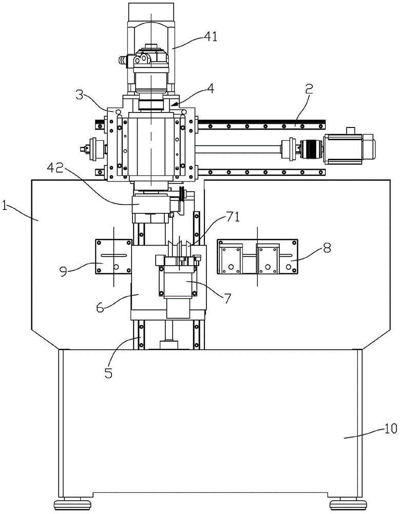
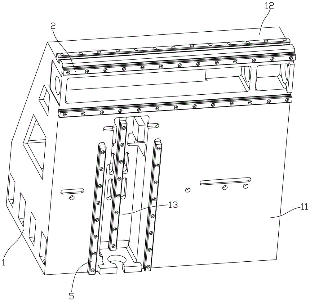
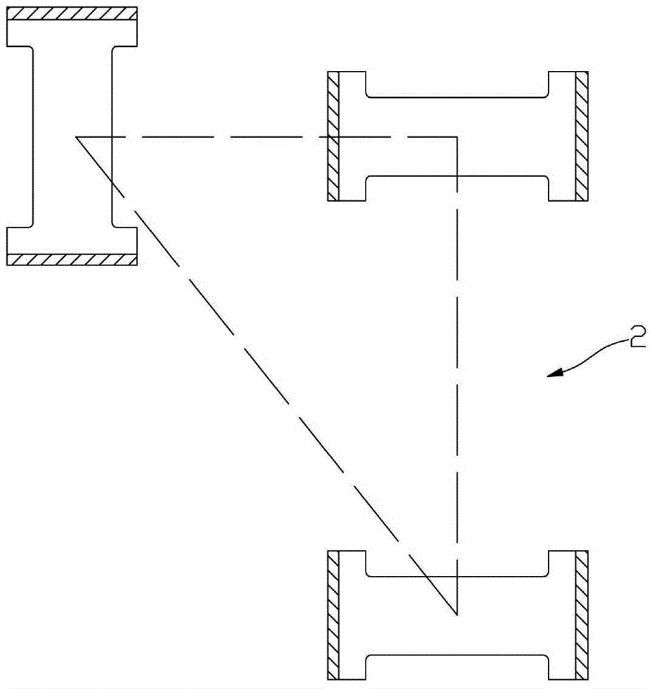
[0025] see Figure 1 to Figure 6 , a two-axis separated inverted CNC lathe according to the present invention, comprising a bed 1, the upper end of the bed 1 is fixedly provided with a transverse guide rail 2, and the transverse guide rails 2 are three in a triangular layout in space The horizontal guide rail 2, the horizontal slide saddle 3 that can move laterally along it is installed on the transverse guide rail 2, the main shaft component unit 4 is installed on the described horizontal slide saddle 3, and the main shaft component unit 4 includes a main shaft 41 and is arranged on the main shaft 41 The spindle chuck 42 at the lower end;

[0026] A longitudinal guide r...


PUM


Abstract

The invention discloses an inverted numerically-controlled lathe provided with two separated shafts. The lathe comprises a lathe body, wherein transverse guide rails are fixedly arranged at the upper end of the lathe body and are three horizontal guide rails triangularly arranged in space, a horizontal slide saddle capable of transversely moving along the transverse guide rails is mounted on the transverse guide rails, and a spindle component unit is mounted on the horizontal slide saddle and comprises a spindle and a spindle chuck arranged at the lower end of the spindle; longitudinal guide rails are fixedly arranged on the lathe body below the transverse guide rails and are three vertical guide rails triangularly arranged in space, a vertical slide saddle capable of longitudinally moving along the longitudinal guide rails is mounted on the longitudinal guide rails, and a tool rest is mounted on the vertical slide saddle; a feeding device and a discharging device are arranged on the lathe body on two sides of the longitudinal guide rails respectively. The guide rails adopt three-dimensional layout in the space, the rigidity of the inverted numerically-controlled lathe is increased, the spindle and the tool rest are used as two feed shafts to move, feeding and discharging of workpieces are realized, and the precision and the stability of the numerically-controlled lathe are improved.

Description

Technical field: [0001] The invention relates to the technical field of numerical control machine tools, in particular to a high-rigidity inverted numerical control lathe which is used for processing disc-like revolving parts. Background technique: [0002] With the development of manufacturing equipment technology, the requirements for using lathes to process various discs, shafts, sleeves, covers, wheels and shell-type rotary parts are getting higher and higher. More and more enterprises use CNC lathes for turning. The CNC lathe has functional flexibility. When changing the processing parts, the processing of the lathe can be changed by calling the corresponding CNC processing program. Therefore, when using the CNC lathe for batch processing, the operator actually only plays the role of loading and unloading. Under the processing method of manual loading and unloading, the operators are not only labor-intensive and tense, but also one person can only operate one lathe. I...

Claims


Application Information

Patent Timeline
Patent Type & Authority Patents(China)
IPC IPC(8): B23B3/06B23B15/00B23Q1/01
CPCB23B3/06B23Q1/017B23Q7/00
Inventor 李鹭扬王心成
Owner 李鹭扬
Why Eureka
Try Eureka