Power transmission method of high-efficiency energy-saving elevator

A power transmission, high-efficiency and energy-saving technology, applied in the field of elevators, can solve problems such as affecting the quality of elevator operation, mechanical failure, affecting the safe operation of elevators, etc.

Inactive Publication Date: 2015-09-02
李先登
View PDF6 Cites 1 Cited by
  • Summary
  • Abstract
  • Description
  • Claims
  • Application Information

AI Technical Summary

Problems solved by technology

[0005] The high-efficiency energy-saving elevator has the advantages of large capacity, high efficiency and energy saving, and can save a lot of building area resources. It adapts to the development trend of modern high-rise buildings and has great market development prospects. As a high-performance elevator, it should be more technically refined, especially There should be more detailed considerations in the power transmission, just imagine: in a 600-meter-high building, a high-efficiency energy-

Method used


Image

  • Power transmission method of high-efficiency energy-saving elevator
  • Power transmission method of high-efficiency energy-saving elevator

Examples


Embodiment approach

[0004] The power transmission part of the original elevator has not been described, and the method is relatively general. It is only mentioned that the upper and lower pairs of sprocket sets are fixed central moments, and the power transmission device can be installed on the two upper sprockets and / or the two lower chains. wheels to drive the elevator to run. This power transmission part can adopt various methods, and the best and most reasonable method is not given; as an embodiment of the present invention, the power transmission part of the power transmission part is placed The root through shaft, through two power pinion gears occludes and drives two power gears on both sides, and then transmits two large chain cable pulleys, chain cable combination ropes and the multi-car operation work on it.

[0005] The high-efficiency energy-saving elevator has the advantages of large capacity, high efficiency and energy saving, and can save a lot of building area resources. It adapts ...

Embodiment 1

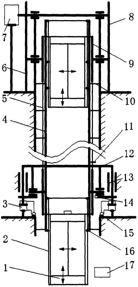
[0016] figure 1 The functional division of the chain pulley 9 of the medium and high-efficiency energy-saving elevator: the power transmission device 7 of the power transmission is arranged on the upper part of the roof, and the two large sprockets 9 on the upper part undertake the tasks of power drive, load bearing and transmission guidance of the elevator. The upper two chain cable pulleys 9 adopt a fixed machine base, which has good stability and load-carrying capacity. The two large sprocket pulleys 9 at the bottom of the building are responsible for adjusting the center distance of the power sprocket 9 of the elevator, part of the load bearing and transmission guidance tasks of the elevator. In the lower part of the building, the adjustment of the center distance is the most convenient and easy, so the functional division scheme using the above-mentioned design is more in line with the requirements of mechanical design;

[0017] The two chain cable wheels 9 on the upper p...


PUM


Abstract

The invention relates to a power transmission method of a high-efficiency energy-saving elevator. According to a power transmission scheme, two large chain wheels on the upper portion of a roof bear the elevator, and also have a power driving function and a transmission guiding function; and two large chain wheels on the lower portion of a bottom have a chain wheel center distance adjusting function, bear part of the elevator and have a transmission guiding function. A function allocation scheme in the design can meet requirements of a mechanical design principle; two chain wheel seats on the lower portion of the bottom are modified into sliding seats capable of sliding vertically, and the heights of the sliding seats can be adjusted hydraulically; the sliding seats are connected to a piston rod of a single-piston cylinder below the sliding seats; and a base of the single-piston cylinder is connected to a horizontal seat surface in a hinged manner. By the seats, a center distance between the upper chain wheel and the lower chain can be adjusted in time according to tension detection of chain cables and horizontal height comparison detection of two ends of each seat, and power transmission of the high-efficiency energy-saving elevator is in an optimal mechanical state during working of the high-efficiency energy-saving elevator; and the elevator can work smoothly, stably and safely, and noises are small.

Description

technical field [0001] The invention relates to an elevator, in particular to a power transmission method for a high-efficiency energy-saving elevator. technical background [0002] In order to adapt to the development trend of modern population to urban filling, to facilitate and meet the living needs of urban population living buildings, and to better adapt to and complete the task of transporting up and down modern high-rise buildings, people have been researching and inventing various types of high-performance elevators. [0003] CN104129696 A has announced a kind of high-efficiency energy-saving elevator, and its technical scheme is to change the elevator that runs straight up and down in a vertical line segment between the traditional single car and the height of the building into two vertical line segments and two vertical lines between the height of the building. It is a plane closed-loop combined line composed of three arcs, which is a circular operation elevator. I...

Claims


Application Information

Patent Timeline
IPC IPC(8): B66B11/04
CPCB66B11/0423B66B11/08
Inventor 李先登黄明迪李丹陈艳红
Owner 李先登
Why Eureka
Try Eureka