
Reverse downstream waterpower automatic gate

A hydraulic automatic and sluice technology, applied in waterway systems, water conservancy projects, water supply devices, etc., can solve problems such as inconvenient maintenance, high energy consumption, and environmental pollution

Active Publication Date: 2015-09-02
WUHAN SHENGYU DRAINING SYST
View PDF5 Cites 6 Cited by
  • Summary
  • Abstract
  • Description
  • Claims
  • Application Information

AI Technical Summary

Problems solved by technology

The gate needs to discharge flood according to different water levels, which requires power drive, consumes a lot of energy, and is not convenient for maintenance
However, when the water level of the storage tank itself is high, overflowing into the storage tank will cause the water to overflow and cause environmental pollution.

Method used


Image

  • Reverse downstream waterpower automatic gate
  • Reverse downstream waterpower automatic gate
  • Reverse downstream waterpower automatic gate

Examples


Embodiment Construction

[0024] The present invention will be further described in detail below in conjunction with the accompanying drawings and specific embodiments to facilitate a clear understanding of the present invention, but they do not limit the present invention.

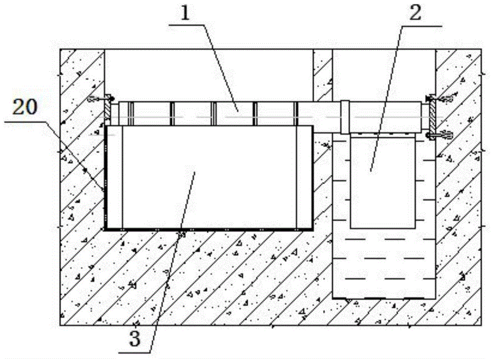
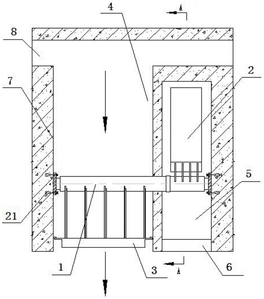
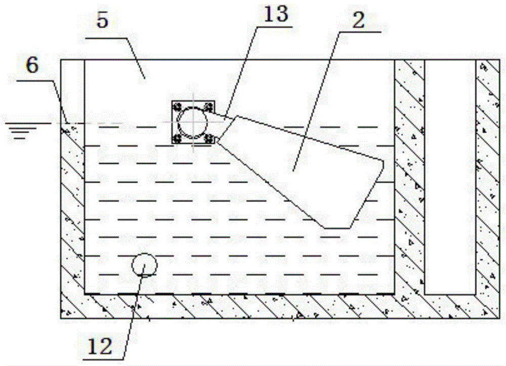
[0025] Such as Figure 1-4 As shown, the present invention includes a buffer tank 8 arranged in the flow channel 4 , a storage tank 9 arranged downstream of the buffer tank 8 , and the maximum water level of the storage tank 9 is lower than that of the buffer tank 8 . The gate 3 is installed between the buffer tank 8 and the storage tank 9, the two side edges and the bottom edge of the gate 3 are respectively sealed with the flow channel walls 7 on both sides of the flow channel 4, and the gate 3 is fixed on one side of the rotating shaft 1 , the two ends of the rotating shaft 1 are respectively hinged on the flow channel walls 7 on both sides of the flow channel 4 , the flow channel walls 7 on both sides of the flow channel 4 are...


PUM


Abstract

The invention belongs to the technical field of drainage system equipment, and specifically relates to a reverse downstream waterpower automatic gate. The reverse downstream waterpower automatic gate comprises a buffering pool arranged inside a flow passage, a pondage regulating pool arranged at the downstream of the buffering pool, and a gate arranged between the buffering pool and the pondage regulating pool. The edges on bilateral sides of the gate and the edge at the bottom of the gate are respectively in hermetic fit with flow passage walls on bilateral sides of the flow passage. The gate is fixed on one side of a spindle. Two ends of the spindle are respectively hinged with the flow passage walls on bilateral sides of the flow passage. The reverse downstream waterpower automatic gate further comprises a floating chamber arranged inside the flow passage. The top of a lateral wall of the floating chamber facing to one side of the pondage regulating pool is provided with a water inlet communicated with the pondage regulating pool. The other side of the spindle is fixedly connected with a floating box which is arranged inside the floating chamber. The bottom of a lateral wall of the floating chamber is provided with a water outlet which is communicated with the flow passage. The gate can be opened with the help of the gravity of the floating box, without an external power or a control measure, thereby allowing the water in the buffering pool to be drained when the water level of the underground pondage regulating pool is low, accordingly achieving the flood discharge timely, and closing the gate when the water level is high.

Description

technical field [0001] The invention belongs to the technical field of drainage system equipment, and in particular relates to a reverse downstream hydraulic automatic gate. Background technique [0002] In the system where municipal rainwater or sewage pipe network overflows to natural water bodies (rivers, lakes, etc.), the water level is often controlled by gates. The gates need to discharge floods according to different water levels, need to be driven by power, consume a lot of energy, and are not easy to maintain. And when the water level of the storage tank itself is high, overflowing in the storage tank will cause the water to overflow and cause environmental pollution. Therefore, how to design a gate structure that has a simple structure, does not consume energy, and can control whether the overflow is based on the water level of the storage tank is a problem that is currently faced. Contents of the invention [0003] The object of the present invention is to sol...

Claims


Application Information

Patent Timeline
Patent Type & Authority Applications(China)
IPC IPC(8): E03F7/04E02B7/40
Inventor 李习洪周超
Owner WUHAN SHENGYU DRAINING SYST
Learn More