An automatic door lock assembly device

An automatic door lock and assembly technology, applied in the direction of building locks, buildings, building structures, etc., to achieve the effect of increasing service life, simple structure and smooth movement

Inactive Publication Date: 2017-12-08
河北那世界工业设计有限公司
View PDF3 Cites 0 Cited by
  • Summary
  • Abstract
  • Description
  • Claims
  • Application Information

AI Technical Summary

Problems solved by technology

[0008] The automatic door locking assembly device of the present invention is simple in structure and easy to operate, which not only solves the problem of needing to insert the key again to lock the door, but also makes the door locking method simple, and the power of locking the door comes from the rotation of the gear of the mechanism, Releases coil spring torque for smooth movement

Method used


Image

  • An automatic door lock assembly device
  • An automatic door lock assembly device
  • An automatic door lock assembly device

Examples


Embodiment 1

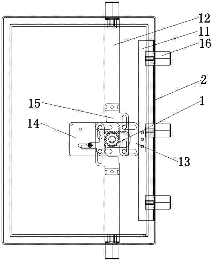
[0039] As the above-mentioned automatic locking door assembly device, the difference of this embodiment is that, refer to image 3 As shown, it is the overall structure diagram of Embodiment 1 of the automatic door lock assembly device of the present invention; the assembly device also includes a lock bolt guide plate 11, two bolt head frames 12, and a first transverse latch plate 13. A second horizontal latch plate 14, two longitudinal latch plates 15 and a plurality of bolt heads 16, wherein the lock bolt guide plate 11 is connected with the door panel 2 for laterally guiding the bolt heads The bolt head frame 12 is respectively located on the upper and lower sides of the door panel 2, one end of the bolt head frame 12 is connected with the door panel 2, and the other end is connected with an end of the longitudinal latch plate 15, the bolt The head frame 12 is used for the longitudinal guidance of the bolt head; the other end of the longitudinal latch plate 15 is engaged wi...

Embodiment 2

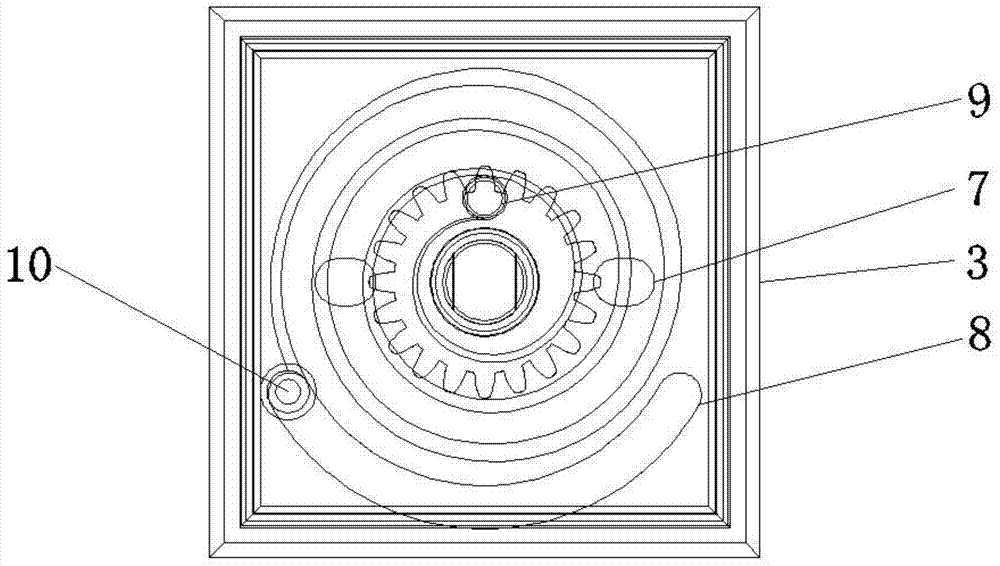
[0046] As the above-mentioned automatic locking door assembly device, the difference of this embodiment is that, refer to Figure 9 As shown, it is a partial front view of Embodiment 2 in the automatic locking door assembly device of the present invention; Figure 10 As shown, it is a partial top view of Embodiment 2 of the automatic locking door assembly device of the present invention; the assembly device also includes a lock bolt control piece 17, and the main body of the lock bolt control piece 17 is a strip-shaped plate structure, One end is a fixed end 171, which is connected with the door panel 2 in a specific application to obtain the effect of fixing one end; the other end is an operating end 172, which is used to limit and release the limit bolt head 16 from extending out of the outer frame in a specific application Perform locking action.

[0047] When the safe door lock needs to be opened, the bolt head frame 12 and the bolt head 16 are retracted, and the safe doo...

Embodiment 3

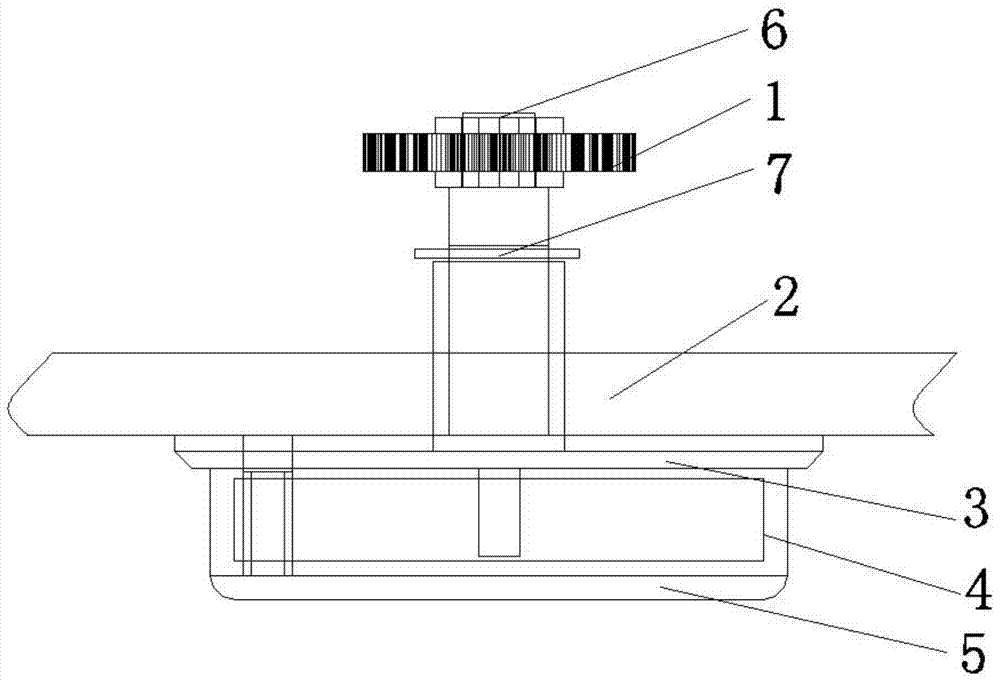
[0051] As the above-mentioned automatic locking door assembly device, the difference of this embodiment is that the overall structure of the first embodiment is combined with the lock bolt control piece 17 in the second embodiment, refer to Figure 11 As shown, it is the overall structure diagram of the third embodiment of the automatic door lock assembly device of the present invention. When unlocking, insert the key, twist the handle 5, and make the coil spring 4 generate torque, and make the The coil spring positioning column 10 of the second handle seat moves in the chute 8, and at the same time, the rotation of the handle 5 passes through the mandrel 6, driving the rotation of the mechanism gear 1, so that the first transverse lock The latch plate 13, the second transverse latch plate 14 and the longitudinal latch plate 15 all move towards each other, and drive the horizontal bolt head and the longitudinal bolt head to shrink inwardly, thereby opening the safe door, and th...


PUM


Abstract

The invention provides an automatic door lock assembly device, the assembly device includes a mechanism gear, a turn handle seat, a coil spring, a turn handle and a mandrel, wherein one end of the mandrel is nested with the mechanism gear, The other end is connected with the handle base, and the mechanism gear is used for force transmission; one side of the handle base is connected with the door panel, and the other side is connected with the handle; the coil spring is installed in the handle, so that the handle Under the action of the above-mentioned coil spring, the generated torque keeps the handle in a locked state. When the door needs to be opened, the handle overcomes the torque of the coil spring and is driven by the gear of the mechanism, and the assembly device returns to the door to open. When the door needs to be locked, the coil spring returns to its original state to lock the door. The automatic door locking assembly device of the present invention is simple in structure and easy to operate, which not only solves the problem of needing to insert the key again to lock the door, but also makes the door locking method simple, and the power of locking the door comes from the rotation of the gear of the mechanism, Releases coil spring torque for smooth motion.

Description

technical field [0001] The invention relates to a door lock, in particular to an automatic door lock assembly device. Background technique [0002] With the development of science and technology, today's safes have developed from the simplest anti-theft function to almost innumerable types such as anti-theft, fire prevention, anti-theft / fire prevention, anti-magnetic, household, commercial, hotel, gun, and file / data. [0003] In the application technology of the existing safe, when the key is used to drive the lock bolt head back into the outer frame to open the cabinet door, at this time the internal tension spring in the safe is in a compressed state, so that the lock bolt head is kept in a compressed state. However, if the safe is to be locked again, it is necessary to turn the key again to drive the lock bolt head, so that the internal extension spring is in a relaxed state, so that the lock bolt head is inserted into the lock bolt hole, and the door is closed and locked...

Claims


Application Information

Patent Timeline
Patent Type & Authority Patents(China)
IPC IPC(8): E05B15/00
Inventor 黄伟君
Owner 河北那世界工业设计有限公司
Why Eureka
Try Eureka