Novel output shaft clutch type gearbox

A technology for output shafts and clutches, which is applied to vehicle gearboxes, instruments, transportation and packaging, etc. It can solve problems such as high driving technical requirements, difficulty in shifting gears, and complex structure of gearboxes, so as to improve service life and operation Reliability, improve the smoothness of operation, and realize the effect of shifting gears on the move

Active Publication Date: 2015-09-02
TIANJIN VOCATIONAL INST
View PDF7 Cites 1 Cited by
  • Summary
  • Abstract
  • Description
  • Claims
  • Application Information

AI Technical Summary

Problems solved by technology

However, there are some problems in the gearboxes of the three modes: the gearboxes of the sliding gear shifting and the meshing sleeve shifting modes all have the problem of difficult shifting, because in the shifting process, when the input shaft power from the engine is cut off, The output shaft will still input power from the wheels to the gearbox in the opposite direction, resulting in tooth beating during gear shifting
At present, the first method to solve this problem is to improve the driver's driving skills, so that it can accurately grasp the speed ratio of the input shaft and the output shaft when shifting gears, and find the shift points of each gear position, but this method is very difficult for the driver. The driving technical requirements are relatively high, which is not easy to realize; the second is to use a synchronizer in the gearbox, that is, a gearbox that uses a synchronizer to shift gears. Although the shifting smoothness of the synchronizer shifting is relatively high, each synchronizer can only To ensure the shifting operation of two gears, the structure of the gearbox for synchronizer shifting is relatively complicated and the manufacturing cost is high. Moreover, the synchronizing ring in the synchronizer is made of copper material, which has low life and reliability

Method used


Image

  • Novel output shaft clutch type gearbox
  • Novel output shaft clutch type gearbox
  • Novel output shaft clutch type gearbox

Examples


Embodiment Construction

[0020] The present invention will be described in further detail below through specific examples. The following examples are only descriptive, not restrictive, and cannot limit the protection scope of the present invention.

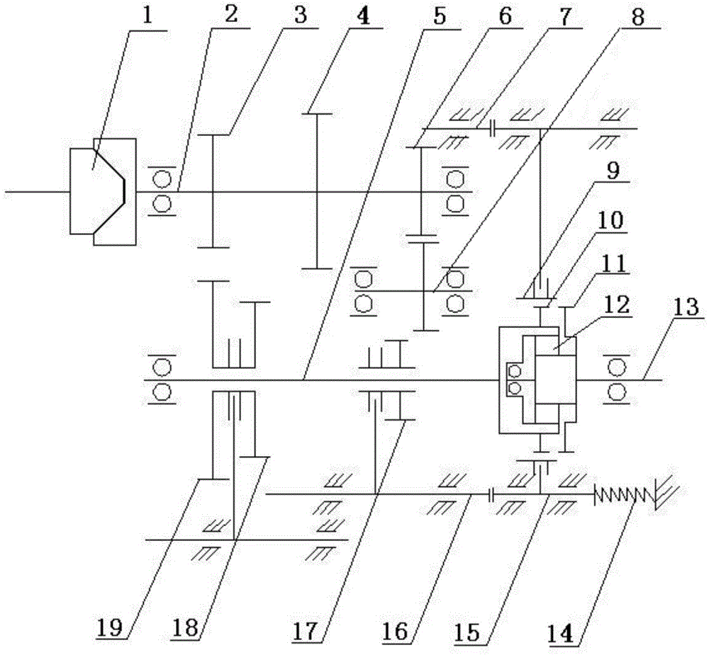
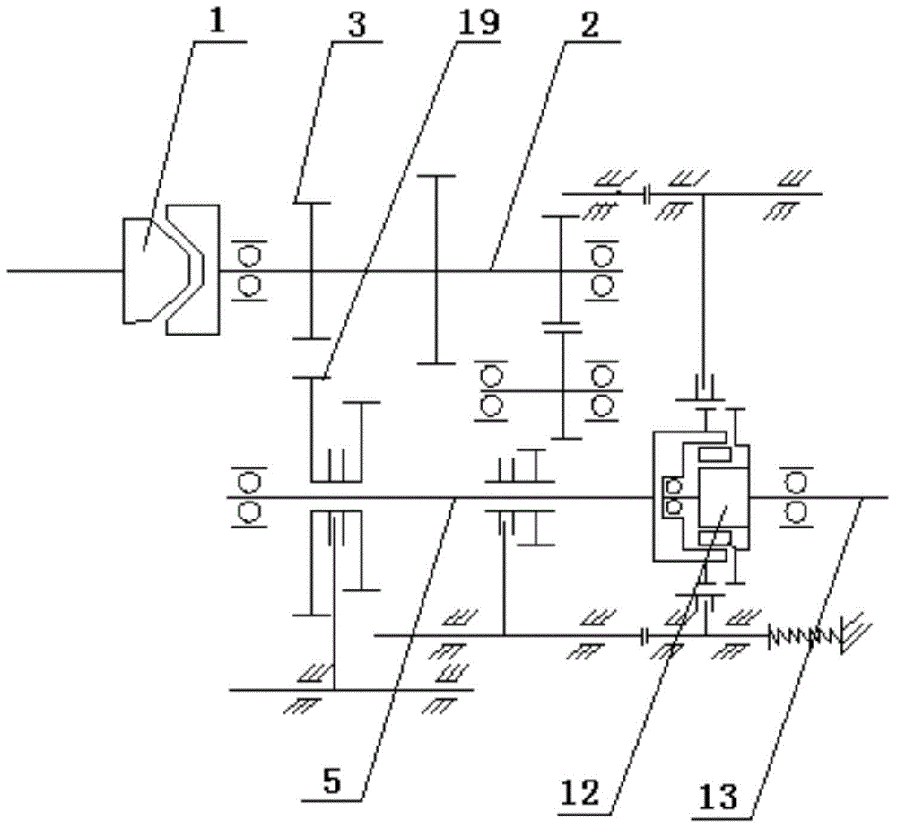
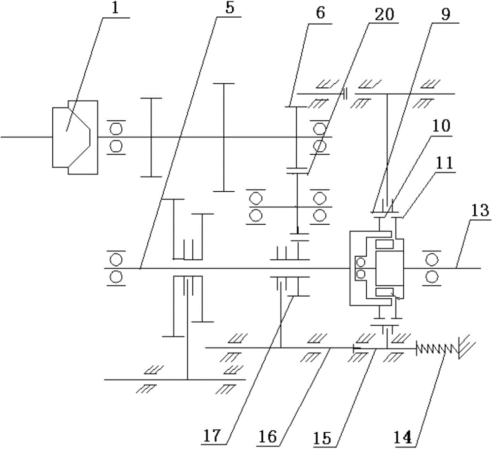
[0021] A new type of output shaft clutch type gearbox, including input shaft clutch 1, input shaft 2, input shaft first driving gear 3, input shaft second driving gear 4, input shaft reverse gear driving gear 6, intermediate shaft 8, mounted on Reverse gear intermediate gear 20, output shaft, output shaft sliding gear set and reverse gear sliding gear 17 on the intermediate shaft. The output shaft sliding gear set is composed of the output shaft first sliding gear 19 and the output shaft second sliding Gear 18 constitutes.

[0022] An input shaft clutch is installed on the input shaft, which is used to combine or cut off the engine power. On the input shaft, the first driving gear of the input shaft, the second driving gear of the input shaft and the reve...


PUM


Abstract

The invention relates to a novel output shaft clutch type gearbox. The novel output shaft clutch type gearbox comprises an input shaft clutch, an input shaft, an input shaft driving gear set, an input shaft reversing driving gear, a medium shaft, a reversing medium gear mounted on the medium shaft, an output shaft, an output shaft sliding gear set and a reversing sliding gear, wherein the input shaft clutch is mounted at the input end of the input shaft; the input shaft driving gear set and the input shaft reversing driving gear are mounted on the input shaft; the output shaft sliding gear set and the reversing sliding gear are mounted on the output shaft and are both hung to a shifting fork to achieve shift. The novel output shaft clutch type gearbox further comprises an output shaft clutch and an output shaft clutch locking mechanism; the output shaft consists of a front section and a rear section; an output shaft clutch is arranged between the front section and the rear section. The novel output shaft clutch type gearbox has the advantages of being smooth to shift, easy to operate, simple in structure, small in manufacturing cost, high in practicability, long in service life and high in reliability.

Description

technical field [0001] The invention belongs to the field of automobiles, tractors, engineering machinery and other ground motorized equipment requiring speed change, and relates to a gearbox for shifting through sliding gears, synchronizers or meshing sleeves, in particular to a novel output shaft clutch type gearbox. Background technique [0002] At present, there are three main modes of gear shifting in manual shifting transmissions for vehicles: sliding gear shifting, meshing sleeve shifting and synchronizer shifting. However, there are some problems in the gearboxes of the three modes: the gearboxes of the sliding gear shifting and the meshing sleeve shifting modes all have the problem of difficult shifting, because in the shifting process, when the input shaft power from the engine is cut off, The output shaft will still input power from the wheels to the gearbox in reverse, resulting in gear rattling during gear shifting. At present, the first method to solve this pr...

Claims


Application Information

Patent Timeline
Patent Type & Authority Applications(China)
IPC IPC(8): F16H3/18F16H61/14F16H3/10F16H63/32F16H63/34
CPCF16H3/10F16H3/18F16H61/14F16H61/148F16H63/32F16H63/34F16H63/3408F16H2200/2033F16H2306/00
Inventor 成起强
Owner TIANJIN VOCATIONAL INST
Why Eureka
Try Eureka